
Page 211 - Electrical Equipment Handbook _ Troubleshooting and Maintenance
P. 211
VARIABLE-SPEED DRIVES
10.10 CHAPTER TEN
Material Expansion coefficient, in/(in °C)
Silicon 4.2 10 6
Copper 16.5 10 6
Aluminum 8.5 10 6
Iron 11.7 10 6
Molybdenum 4.9 10 6
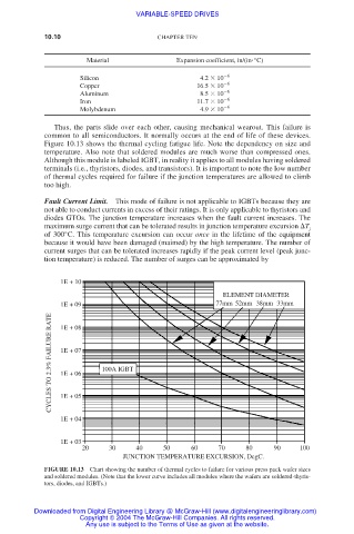
Thus, the parts slide over each other, causing mechanical wearout. This failure is
common to all semiconductors. It normally occurs at the end of life of these devices.
Figure 10.13 shows the thermal cycling fatigue life. Note the dependency on size and
temperature. Also note that soldered modules are much worse than compressed ones.
Although this module is labeled IGBT, in reality it applies to all modules having soldered
terminals (i.e., thyristors, diodes, and transistors). It is important to note the low number
of thermal cycles required for failure if the junction temperatures are allowed to climb
too high.
Fault Current Limit. This mode of failure is not applicable to IGBTs because they are
not able to conduct currents in excess of their ratings. It is only applicable to thyristors and
diodes GTOs. The junction temperature increases when the fault current increases. The
maximum surge current that can be tolerated results in junction temperature excursion T
j
of 300°C. This temperature excursion can occur once in the lifetime of the equipment
because it would have been damaged (maimed) by the high temperature. The number of
current surges that can be tolerated increases rapidly if the peak current level (peak junc-
tion temperature) is reduced. The number of surges can be approximated by
1E + 10
ELEMENT DIAMETER
1E + 09 77mm 52mm 38mm 33mm
CYCLES TO 2.3% FAILURE RATE 1E + 07 100A IGBT
1E + 08
1E + 06
1E + 05
1E + 04
1E + 03
20 30 40 50 60 70 80 90 100
JUNCTION TEMPERATURE EXCURSION, DegC.
FIGURE 10.13 Chart showing the number of thermal cycles to failure for various press pack wafer sizes
and soldered modules. (Note that the lower curve includes all modules where the wafers are soldered-thyris-
tors, diodes, and IGBTs.)
Downloaded from Digital Engineering Library @ McGraw-Hill (www.digitalengineeringlibrary.com)
Copyright © 2004 The McGraw-Hill Companies. All rights reserved.
Any use is subject to the Terms of Use as given at the website.