
Page 215 - Electrical Equipment Handbook _ Troubleshooting and Maintenance
P. 215
VARIABLE-SPEED DRIVES
10.14 CHAPTER TEN
the insulation corona discharge level (partial discharge level), the insulation will degrade
with each voltage pulse. It will eventually fail.
The new “inverter-rated” motors have triple-layer insulation. They have a 1600- to
2000-V partial discharge level. This allows them to withstand double the voltage peak tran-
sient from a 600-V inverter. Since most “standard” induction motors can withstand about
1200 V, its use in this application will shorten its life drastically. It can be as low as a few
hours only.
Motor Winding Voltage Distribution
All high-frequency transient voltages tend to be unevenly distributed across the motor
windings. The high frequencies develop greater voltages across the first windings rather
than being evenly distributed across the whole length of the windings. The effect of high-
frequency transients tends to be accentuated on the first few windings. This is where most
motor insulation failures occur. The problem becomes worse when the frequency of the
transients (i.e., the IGBT switching speed) is higher.
This problem does not occur with drives using older transistors or GTOs because the
switching speeds are much lower (2 to 4 s). When the drive uses IGBTs with switching
speeds of 50 to 150 ns, the motor should be connected to the inverter by a cable shorter than
20 ft, or special precautions should be taken.
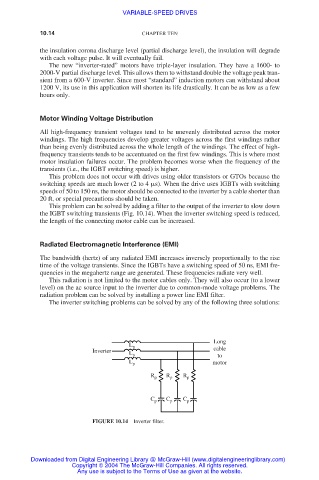
This problem can be solved by adding a filter to the output of the inverter to slow down
the IGBT switching transients (Fig. 10.14). When the inverter switching speed is reduced,
the length of the connecting motor cable can be increased.
Radiated Electromagnetic Interference (EMI)
The bandwidth (hertz) of any radiated EMI increases inversely proportionally to the rise
time of the voltage transients. Since the IGBTs have a switching speed of 50 ns, EMI fre-
quencies in the megahertz range are generated. These frequencies radiate very well.
This radiation is not limited to the motor cables only. They will also occur (to a lower
level) on the ac source input to the inverter due to common-mode voltage problems. The
radiation problem can be solved by installing a power line EMI filter.
The inverter switching problems can be solved by any of the following three solutions:
Long
L p
Inverter L p cable
to
L p motor
R p R p R p
C p C p C p
FIGURE 10.14 Inverter filter.
Downloaded from Digital Engineering Library @ McGraw-Hill (www.digitalengineeringlibrary.com)
Copyright © 2004 The McGraw-Hill Companies. All rights reserved.
Any use is subject to the Terms of Use as given at the website.