
Page 217 - Electrical Equipment Handbook _ Troubleshooting and Maintenance
P. 217
VARIABLE-SPEED DRIVES
10.16 CHAPTER TEN
The cable insulation problem must also be addressed. A 2000-V cable should be used
(depending on the length of the connecting cable) for a 600-V IGBT inverter. This solution
does not reduce the waveform rise time. Therefore, it does not address the motor bearing
current or EMI radiation problems.
CABLING DETAILS FOR AC DRIVES
The cable connections from the inverter to the motor and ground are important details
required to achieve a successful ac drive installation due to the fast switching rates. These
details are applicable for the ac drives. However, they are mandatory for IGBT drives due
to the higher switching rates. If this information is not properly followed, problems can
occur in the motor and cable insulation, bearings, or EMI.
The most important criterion for power cabling is the symmetry of the cable and
grounding practices. The symmetry is required to ensure cancellation of any stray fluxes.
This will minimize the bearing currents and EMI radiation. The components within the
inverter should also be symmetric.
CABLE DETAILS
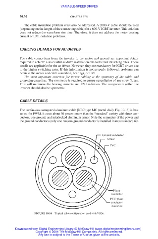
The continuous corrugated aluminum cable [NEC type MC (metal clad), Fig. 10.16] is best
suited for PWM. It costs about 30 percent more than the “standard” variety with three con-
ductors, one ground, and interlocked aluminum armor. Note the symmetry of the power and
the ground conductors (only one random ground conductor is installed in most standard 60-
Ground conductor
Armor
PVC
Phase
conductor
PVC phase
conductor
insulation
FIGURE 10.16 Typical cable configuration used with VSDs.
Downloaded from Digital Engineering Library @ McGraw-Hill (www.digitalengineeringlibrary.com)
Copyright © 2004 The McGraw-Hill Companies. All rights reserved.
Any use is subject to the Terms of Use as given at the website.