
Page 216 - Electrical Equipment Handbook _ Troubleshooting and Maintenance
P. 216
VARIABLE-SPEED DRIVES
VARIABLE-SPEED DRIVES 10.15
Cable Terminating (Matching) Impedance
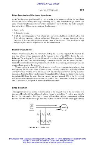
An RC (resistance-capacitance) filter can be added to the motor terminals. Its impedance
should match that of the connecting cable (Fig. 10.15). The reflected voltage will be can-
celed by removing the discontinuity of the impedance. This will reduce the motor and cable
insulation stress. This solution has three disadvantages:
● Cost is high.
● It dissipates power.
● The filter must be added in a very inhospitable environment at the motor termination box.
This solution prevents voltage reflection. Therefore, it reduces insulation stress.
However, it does not change the switching speed of the inverter. Thus, the high voltage
rise (dυ/dt) will still be impressed on the motor insulation.
Inverter Output Filter
When a filter is added, like the one shown in Fig. 10.14, at the output of the inverter, the
rise time of the voltage transients will be reduced to that of the GTOs due to the series
inductors. The voltage reflection problems will be reduced significantly due to the decrease
in voltage rise time. This will allow longer cables to the motor. The RC part of the filter is
needed to dampen the switching transients. This filter is also costly, dissipates power, and
requires large space in the inverter.
The most effective type of this filter is a large one that prevents switching voltages from
propagating. In this case, there will not be any switching, insulation, or EMI problems.
This type would be ideal for a drive used with an existing older motor having a suspect
insulation. Since the filter’s inductances have reduced the voltage rise times to the motor,
the radiated EMI and the motor bearing currents are also reduced. This is the best overall
solution (even with the increase in cost). In general, this is a standard part of the inverter,
or it is available as an option in most commercial inverters.
Extra Insulation
This approach involves adding extra insulation to the magnet wire in the motor and con-
necting cable to handle the additional voltage caused by switching. A typical insulation for
inverter duty motors has three layers. It can withstand the voltage transients of a 600-V
inverter without corona discharge (standard motors cannot be used for these applications).
Long
cable
from Motor
inverter
R p R p R p
C p C p C p
FIGURE 10.15 Motor filter.
Downloaded from Digital Engineering Library @ McGraw-Hill (www.digitalengineeringlibrary.com)
Copyright © 2004 The McGraw-Hill Companies. All rights reserved.
Any use is subject to the Terms of Use as given at the website.