
Page 218 - Electrical Equipment Handbook _ Troubleshooting and Maintenance
P. 218
VARIABLE-SPEED DRIVES
VARIABLE-SPEED DRIVES 10.17
Hz power cables). The symmetry helps in canceling most of the stray fluxes. The symmetry
in the cable also helps to reduce bearing currents and EMI (by providing better shielding).
Motor, Cable, and Power System Grounding
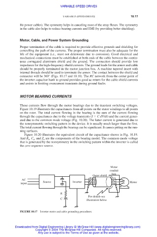
Proper termination of the cable is required to provide effective grounds and shielding for
controlling the path of the currents. The proper termination must also be adequate for the
life of the equipment (i.e., must not deteriorate due to corrosion). Good electrical and
mechanical connections must be established at both ends of the cable between the contin-
uous corrugated aluminum shield and the ground. The connection should provide low
impedance for the high-frequency shield currents. The ground leads for the armor and cable
should be properly terminated in the motor junction box. A machine tapered insert with
internal threads should be used to terminate the armor. The contact between the shield and
connector will be 360° (Figs. 10.17 and 10.18). The RC network from the center point of
the inverter capacitor bank to ground provides good ac return for the cable shield currents
and assists in limiting overcurrent transients during ground faults.
MOTOR BEARING CURRENTS
These currents flow through the motor bearings due to the transient switching voltages.
Figure 10.19 illustrates the capacitances from all points on the stator windings to all points
on the rotor. The total current flowing in the bearing is the sum of the current flowing
through the capacitances due to the voltage transients (I C dV/dt) and the current gener-
ated due to the common-mode voltage (Fig. 10.20). The latter current is generated due to
the nonsymmetric switching pattern in the device. It is usually much larger than the first.
The total current flowing through the bearing can be significant. It causes pitting on the run-
ning surfaces.
Figure 10.20 illustrates the equivalent circuit of the capacitance shown in Fig. 10.19.
And R , C , and Z are the components of the bearing model. The common-mode voltage
b b b
that is generated by the nonsymmetry in the switching pattern within the inverter is called
the zero sequence source.
Motor
conduit
box
Outer shield
AC
input Source Inverter Motor
R
For details see
C
illustration below
FIGURE 10.17 Inverter motor and cable grounding procedures.
Downloaded from Digital Engineering Library @ McGraw-Hill (www.digitalengineeringlibrary.com)
Copyright © 2004 The McGraw-Hill Companies. All rights reserved.
Any use is subject to the Terms of Use as given at the website.