
Page 208 - Electrical Equipment Handbook _ Troubleshooting and Maintenance
P. 208
VARIABLE-SPEED DRIVES
VARIABLE-SPEED DRIVES 10.7
0.7
0.6
0.5
0.4
0.3
0.2
Current, A –0.1 0
0.1
–0.2
–0.3
–0.4
–0.5
–0.6
–0.7
0 2 4 6
Time, s
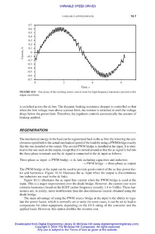
FIGURE 10.9 One phase of the resulting motor current (note the high-frequency harmonics present in this
output waveform).
is switched across the dc bus. The dynamic braking resistance chopper is controlled so that
when the link voltage rises above a preset limit, the resistor is switched in until the voltage
drops below the preset limit. Therefore, the regulator controls automatically the amount of
braking applied.
REGENERATION
The mechanical energy in the load can be regenerated back to the ac line (by lowering the syn-
chronous speed below the actual mechanical speed of the load) by using a PWM bridge exactly
like the one installed at the output. The second PWM bridge is installed at the input. It is iden-
tical to the one used on the output, except that it is turned around so that the ac signal is fed into
the three-phase terminals and the dc signal is connected to the dc input as follows:
Three-phase ac input → PWM bridge → dc link including capacitors and inductors
→ PWM bridge → three-phase ac output
The PWM bridge at the input can be used to provide good control of the ac line power fac-
tor and harmonics. Figure 10.10 illustrates the ac input when the output is discontinuous
(no inductors are used in the dc link).
Figure 10.11 illustrates the ac input line current when the PWM bridge is used at the
input. This is a major improvement over the diode bridge. However, the current sine wave
contains harmonics based on the IGBT carrier frequency (usually 1.4 to 5 kHz). These har-
monics are, in reality, more troublesome than the discontinuous current obtained using the
diode bridge.
The main advantage of using the PWM source bridge at the input is the ability to regu-
late the power factor, which is normally set to unity (in some cases, it can be set to lead to
compensate for other equipment, depending on the kVA rating of the converter and the
applied load). However, this option doubles the inverter cost.
Downloaded from Digital Engineering Library @ McGraw-Hill (www.digitalengineeringlibrary.com)
Copyright © 2004 The McGraw-Hill Companies. All rights reserved.
Any use is subject to the Terms of Use as given at the website.