
Page 202 - Electrical Equipment Handbook _ Troubleshooting and Maintenance
P. 202
Source: ELECTRICAL EQUIPMENT HANDBOOK
CHAPTER 10
VARIABLE-SPEED DRIVES
BASIC PRINCIPLES OF AC VARIABLE-SPEED DRIVES
A variable-speed drive (VSD) is used to drive a motor at variable speed. The main parts of
a VSD are
ac power input
⇓
⇒ ⇒ ⇒ ⇒ mechanical
work output
reference speed and ac⇒dc⇒ac ac motor
generator voltage control inverter
system
The control system of the VSD adjusts the output voltage and frequency so that the ratio of
voltage to frequency remains constant at all times. The two modes of operation are as follows:
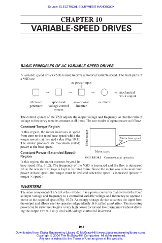
Constant-Torque Region
In this region, the motor increases in speed
from zero to the rated base speed while the
torque remains at the rated value (Fig. 10.1). Motor torque Motor base speed
The motor produces its maximum (rated)
power at the base speed.
Constant-Power (Extended Speed) Motor speed
Region FIGURE 10.1 Constant-torque operation.
In this region, the motor operates beyond its
base speed (Fig. 10.2). The frequency of the VSD is increased and the flux is decreased
while the armature voltage is kept at its rated value. Since the motor was at its maximum
power at base speed, the torque must be reduced when the speed is increased (power
torque speed).
INVERTERS
The main component of a VSD is the inverter. It is a power converter that converts the fixed
ac input voltage and frequency to a controlled variable voltage and frequency to operate a
motor at the required speed (Fig. 10.3). An energy storage device separates the input from
the output and allows each to operate independently. It is called a link filter. The incoming
power can be structured to give a very high power factor and low harmonics without affect-
ing the output (we will only deal with voltage controlled inverters).
10.1
Downloaded from Digital Engineering Library @ McGraw-Hill (www.digitalengineeringlibrary.com)
Copyright © 2004 The McGraw-Hill Companies. All rights reserved.
Any use is subject to the Terms of Use as given at the website.