
Page 196 - Electrical Equipment Handbook _ Troubleshooting and Maintenance
P. 196
POWER ELECTRONICS, RECTIFIERS, AND PULSE-WIDTH MODULATION INVERTERS
POWER ELECTRONICS, RECTIFIERS, AND INVERTERS 9.23
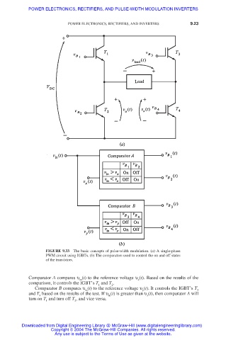
FIGURE 9.33 The basic concepts of pulse-width modulation. (a) A single-phase
PWM circuit using IGBTs. (b) The comparators used to control the on and off states
of the transistors.
Comparator A compares υ (t) to the reference voltage υ (t). Based on the results of the
in x
comparison, it controls the IGBT’s T and T .
1 2
Comparator B compares υ (t) to the reference voltage υ (t). It controls the IGBT’s T
in y 3
and T based on the results of the test. If υ (t) is greater than υ (t), then comparator A will
4 in x
turn on T and turn off T , and vice versa.
1 2
Downloaded from Digital Engineering Library @ McGraw-Hill (www.digitalengineeringlibrary.com)
Copyright © 2004 The McGraw-Hill Companies. All rights reserved.
Any use is subject to the Terms of Use as given at the website.