
Page 189 - Electrical Equipment Handbook _ Troubleshooting and Maintenance
P. 189
POWER ELECTRONICS, RECTIFIERS, AND PULSE-WIDTH MODULATION INVERTERS
9.16 CHAPTER NINE
VOLTAGE VARIATION BY AC PHASE CONTROL
SCRs and TRIACs provide a convenient method for controlling the average voltage
applied to a load by changing the phase angle of the source voltage.
AC Phase Control for a DC Load Driven from an AC Source
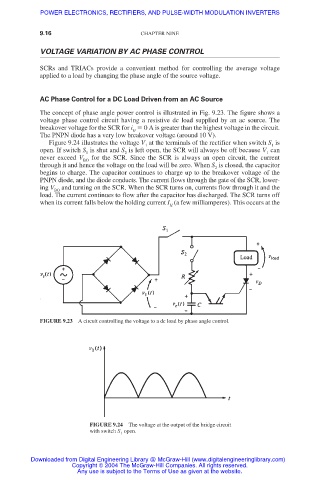
The concept of phase angle power control is illustrated in Fig. 9.23. The figure shows a
voltage phase control circuit having a resistive dc load supplied by an ac source. The
breakover voltage for the SCR for i 0 A is greater than the highest voltage in the circuit.
G
The PNPN diode has a very low breakover voltage (around 10 V).
Figure 9.24 illustrates the voltage V at the terminals of the rectifier when switch S is
1 1
open. If switch S is shut and S is left open, the SCR will always be off because V can
1 2 1
never exceed V BO for the SCR. Since the SCR is always an open circuit, the current
through it and hence the voltage on the load will be zero. When S is closed, the capacitor
2
begins to charge. The capacitor continues to charge up to the breakover voltage of the
PNPN diode, and the diode conducts. The current flows through the gate of the SCR, lower-
ing V and turning on the SCR. When the SCR turns on, currents flow through it and the
BO
load. The current continues to flow after the capacitor has discharged. The SCR turns off
when its current falls below the holding current I (a few milliamperes). This occurs at the
H
FIGURE 9.23 A circuit controlling the voltage to a dc load by phase angle control.
FIGURE 9.24 The voltage at the output of the bridge circuit
with switch S open.
1
Downloaded from Digital Engineering Library @ McGraw-Hill (www.digitalengineeringlibrary.com)
Copyright © 2004 The McGraw-Hill Companies. All rights reserved.
Any use is subject to the Terms of Use as given at the website.