
Page 186 - Electrical Equipment Handbook _ Troubleshooting and Maintenance
P. 186
POWER ELECTRONICS, RECTIFIERS, AND PULSE-WIDTH MODULATION INVERTERS
POWER ELECTRONICS, RECTIFIERS, AND INVERTERS 9.13
A voltage and current pulse is gener-
ated by the transition from the conducting
to the nonconducting region of the device.
Relaxation oscillator is the name given
to the circuit used to generate analog
pulse.
Digital pulse generation circuits are com-
monly used in modern solid-state motor
drives. They use a microcomputer which
executes a program stored in read-only
memory (ROM). The program uses differ-
ent inputs to generate pulses at the proper
time. Common inputs that the program
considers are the desired speed of the
motor, actual speed of the motor, rate of
acceleration or deceleration, and specified
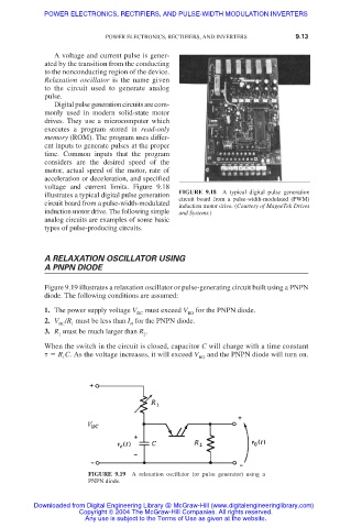
voltage and current limits. Figure 9.18
FIGURE 9.18 A typical digital pulse generation
illustrates a typical digital pulse generation circuit board from a pulse-width-modulated (PWM)
circuit board from a pulse-width-modulated
induction motor drive. (Courtesy of MagneTek Drives
induction motor drive. The following simple and Systems.)
analog circuits are examples of some basic
types of pulse-producing circuits.
A RELAXATION OSCILLATOR USING
A PNPN DIODE
Figure 9.19 illustrates a relaxation oscillator or pulse-generating circuit built using a PNPN
diode. The following conditions are assumed:
1. The power supply voltage V DC must exceed V BO for the PNPN diode.
2. V /R must be less than I for the PNPN diode.
DC
H
1
3. R must be much larger than R .
2
1
When the switch in the circuit is closed, capacitor C will charge with a time constant
R C. As the voltage increases, it will exceed V BO and the PNPN diode will turn on.
1
FIGURE 9.19 A relaxation oscillator (or pulse generator) using a
PNPN diode.
Downloaded from Digital Engineering Library @ McGraw-Hill (www.digitalengineeringlibrary.com)
Copyright © 2004 The McGraw-Hill Companies. All rights reserved.
Any use is subject to the Terms of Use as given at the website.