
Page 5 - Electrical Equipment Handbook _ Troubleshooting and Maintenance
P. 5
FUNDAMENTALS OF ELECTRIC SYSTEMS
1.4 CHAPTER ONE
CURRENT AND RESISTANCE
The electric current i is established in a conductor when a net charge q passes through it in
time t. Thus, the current is
q
i
t
The units for the parameters are
● i: amperes (A)
● q: coulombs (C)
● t: seconds (s)
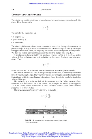
The electric field exerts a force on the electrons to move them through the conductor. A
positive charge moving in one direction has the same effect as a negative charge moving in
the opposite direction. Thus, for simplicity we assume that all charge carriers are positive.
We draw the current arrows in the direction that positive charges flow (Fig. 1.3).
A conductor is characterized by its resistance (symbol ). It is defined as the
voltage difference between two points divided by the current flowing through the con-
ductor. Thus,
V
R
i
where V is in volts, i is in amperes, and the resistance R is in ohms (abbreviated ).
The current, which is the flow of charge through a conductor, is often compared to the
flow of water through a pipe. The water flow occurs due to the pressure difference between
the inlet and outlet of a pipe. Similarly, the charge flows through the conductor due to the
voltage difference.
The resistivity is a characteristic of the conductor material. It is a measure of the
resistance that the material has to the current. For example, the resistivity of copper is
16
1.7 10 8
m; that of fused quartz is about 10
m. Table 1.2 lists some electrical
properties of common metals.
The temperature coefficient of resistivity is given by
1 d
dT
FIGURE 1.3 Electrons drift in a direction opposite to the electric
field in a conductor.
Downloaded from Digital Engineering Library @ McGraw-Hill (www.digitalengineeringlibrary.com)
Copyright © 2004 The McGraw-Hill Companies. All rights reserved.
Any use is subject to the Terms of Use as given at the website.