
Page 8 - Electrical Equipment Handbook _ Troubleshooting and Maintenance
P. 8
FUNDAMENTALS OF ELECTRIC SYSTEMS
FUNDAMENTALS OF ELECTRIC SYSTEMS 1.7
The force F will always be at a right
angle to the plane formed by v and B. Thus,
it will always be a sideways force. The
force will disappear in these cases:
1. If the charge stops moving
2. If v is parallel or antiparallel to the
direction of B
The force F has a maximum value if v is at
a right angle to B ( 90°).
Figure 1.6 illustrates the force created
on a positive and a negative electron mov-
ing in a magnetic field B pointing out of the
plane of the figure (symbol ). The unit of
B is the tesla (T) or weber per square meter
2
(Wb/m ). Thus
FIGURE 1.5 Illustration of F q v B. Test
0
1 N charge q is fired through the origin with velocity v.
2
1 tesla (T) 1 weber/meter 0
A
m
The force acting on a current-carrying conductor placed at a right angle to a magnetic field B
(Fig. 1.7) is given by
F ilB
where l is the length of conductor placed in the magnetic field.
Ampère’s Law
Figure 1.8 illustrates a current-carrying conductor surrounded by small magnets. If there is
no current in the conductor, all the magnets will be aligned with the horizontal component
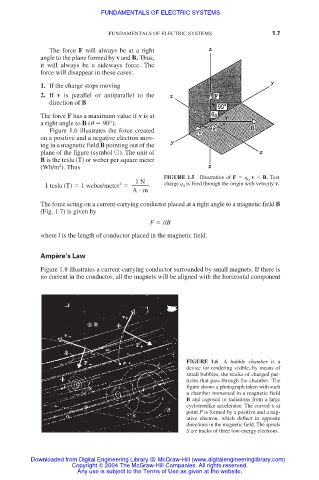
FIGURE 1.6 A bubble chamber is a
device for rendering visible, by means of
small bubbles, the tracks of charged par-
ticles that pass through the chamber. The
figure shows a photograph taken with such
a chamber immersed in a magnetic field
B and exposed to radiations from a large
cyclotronlike accelerator. The curved υ at
point P is formed by a positive and a neg-
ative electron, which deflect in opposite
directions in the magnetic field. The spirals
S are tracks of three low-energy electrons.
Downloaded from Digital Engineering Library @ McGraw-Hill (www.digitalengineeringlibrary.com)
Copyright © 2004 The McGraw-Hill Companies. All rights reserved.
Any use is subject to the Terms of Use as given at the website.