
Page 9 - Electrical Equipment Handbook _ Troubleshooting and Maintenance
P. 9
FUNDAMENTALS OF ELECTRIC SYSTEMS
1.8 CHAPTER ONE
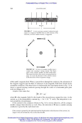
FIGURE 1.7 A wire carrying a current i is placed at right
angles to a magnetic field B. Only the drift velocity of the
electrons, not their random motion, is suggested.
FIGURE 1.8 An array of compass needles near a
central wire carrying a strong current. The black
ends of the compass needles are their north poles.
The central dot shows the current emerging from the
page. As usual, the direction of the current is taken
as the direction of flow of positive charge.
of the earth’s magnetic field. When a current flows through the conductor, the orientation of
the magnets suggests that the lines of induction of the magnetic field form closed circles
around the conductor. This observation is reinforced by the experiment shown in Fig. 1.9. It
shows a current-carrying conductor passing through the center of a horizontal glass plate
with iron filings on it.
Ampère’s law states that
B
dl i
0
where B is the magnetic field, l is the length of the circumference around the wire, i is the
current, is the permeability constant ( 4 10 7 T
m/A). The integration is car-
0 0
ried around the circumference.
If the current in the conductor shown in Fig. 1.8 is reverse direction, all the compass
needles change their direction as well. Thus, the direction of B near a current-carrying
conductor is given by the right-hand-rule:
If the current is grasped by the right hand and the thumb points in the direction of the current, the
fingers will curl around the wire in the direction B.
Downloaded from Digital Engineering Library @ McGraw-Hill (www.digitalengineeringlibrary.com)
Copyright © 2004 The McGraw-Hill Companies. All rights reserved.
Any use is subject to the Terms of Use as given at the website.