
Page 12 - Electrical Equipment Handbook _ Troubleshooting and Maintenance
P. 12
FUNDAMENTALS OF ELECTRIC SYSTEMS
FUNDAMENTALS OF ELECTRIC SYSTEMS 1.11
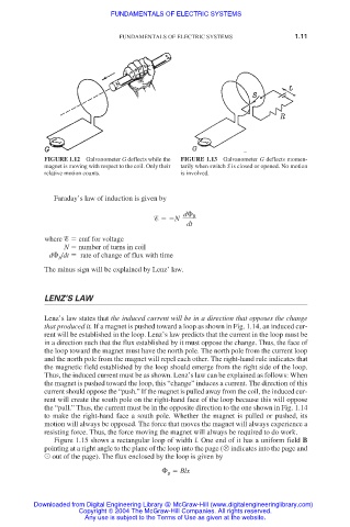
FIGURE 1.12 Galvanometer G deflects while the FIGURE 1.13 Galvanometer G deflects momen-
magnet is moving with respect to the coil. Only their tarily when switch S is closed or opened. No motion
relative motion counts. is involved.
Faraday’s law of induction is given by
d
B
N
dt
where emf for voltage
N number of turns in coil
d
/dt rate of change of flux with time
B
The minus sign will be explained by Lenz’ law.
LENZ’S LAW
Lenz’s law states that the induced current will be in a direction that opposes the change
that produced it. If a magnet is pushed toward a loop as shown in Fig. 1.14, an induced cur-
rent will be established in the loop. Lenz’s law predicts that the current in the loop must be
in a direction such that the flux established by it must oppose the change. Thus, the face of
the loop toward the magnet must have the north pole. The north pole from the current loop
and the north pole from the magnet will repel each other. The right-hand rule indicates that
the magnetic field established by the loop should emerge from the right side of the loop.
Thus, the induced current must be as shown. Lenz’s law can be explained as follows: When
the magnet is pushed toward the loop, this “change” induces a current. The direction of this
current should oppose the “push.” If the magnet is pulled away from the coil, the induced cur-
rent will create the south pole on the right-hand face of the loop because this will oppose
the “pull.” Thus, the current must be in the opposite direction to the one shown in Fig. 1.14
to make the right-hand face a south pole. Whether the magnet is pulled or pushed, its
motion will always be opposed. The force that moves the magnet will always experience a
resisting force. Thus, the force moving the magnet will always be required to do work.
Figure 1.15 shows a rectangular loop of width l. One end of it has a uniform field B
pointing at a right angle to the plane of the loop into the page ( indicates into the page and
out of the page). The flux enclosed by the loop is given by
Blx
B
Downloaded from Digital Engineering Library @ McGraw-Hill (www.digitalengineeringlibrary.com)
Copyright © 2004 The McGraw-Hill Companies. All rights reserved.
Any use is subject to the Terms of Use as given at the website.