
Page 14 - Electrical Equipment Handbook _ Troubleshooting and Maintenance
P. 14
FUNDAMENTALS OF ELECTRIC SYSTEMS
FUNDAMENTALS OF ELECTRIC SYSTEMS 1.13
2 2
B l v
F ilB sin 90°
1
R
The force pulling the loop must do a steady
work given by
2 2 2
B l v
P F v
1
R
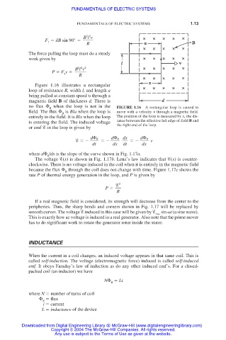
Figure 1.16 illustrates a rectangular
loop of resistance R, width l, and length a
being pulled at constant speed υ through a
magnetic field B of thickness d. There is
no flux
when the loop is not in the FIGURE 1.16 A rectangular loop is caused to
B
field. The flux
is Bla when the loop is move with a velocity v through a magnetic field.
B
entirely in the field. It is Blx when the loop The position of the loop is measured by x, the dis-
is entering the field. The induced voltage tance between the effective left edge of field B and
the right end of the loop.
or emf in the loop is given by
dx d
B
d
B
d
B
v
dt dx dt dx
where d
/dx is the slope of the curve shown in Fig. 1.17a.
B
The voltage (x) is shown in Fig. 1.17b. Lenz’s law indicates that (x) is counter-
clockwise. There is no voltage induced in the coil when it is entirely in the magnetic field
because the flux
through the coil does not change with time. Figure 1.17c shows the
B
rate P of thermal energy generation in the loop, and P is given by
2
P
R
If a real magnetic field is considered, its strength will decrease from the center to the
peripheries. Thus, the sharp bends and corners shown in Fig. 1.17 will be replaced by
smooth curves. The voltage induced in this case will be given by sin t (a sine wave).
max
This is exactly how ac voltage is induced in a real generator. Also note that the prime mover
has to do significant work to rotate the generator rotor inside the stator.
INDUCTANCE
When the current in a coil changes, an induced voltage appears in that same coil. This is
called self-induction. The voltage (electromagnetic force) induced is called self-induced
emf. It obeys Faraday’s law of induction as do any other induced emf’s. For a closed-
packed coil (an inductor) we have
N
Li
B
where N number of turns of coil
flux
B
i current
L inductance of the device
Downloaded from Digital Engineering Library @ McGraw-Hill (www.digitalengineeringlibrary.com)
Copyright © 2004 The McGraw-Hill Companies. All rights reserved.
Any use is subject to the Terms of Use as given at the website.