
Page 19 - Electrical Equipment Handbook _ Troubleshooting and Maintenance
P. 19
FUNDAMENTALS OF ELECTRIC SYSTEMS
1.18 CHAPTER ONE
An Inductive Circuit
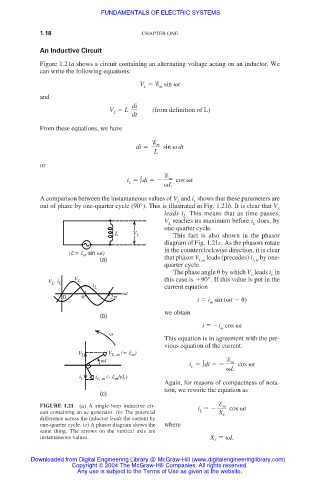
Figure 1.21a shows a circuit containing an alternating voltage acting on an inductor. We
can write the following equations:
V sin t
L m
and
di
V L (from definition of L)
L dt
From these equations, we have
m
di sin dt
L
or
m
i ∫di cos t
L
L
A comparison between the instantaneous values of V and i shows that these parameters are
L
L
out of phase by one-quarter cycle (90°). This is illustrated in Fig. 1.21b. It is clear that V L
leads i This means that as time passes,
L.
V reaches its maximum before i does, by
L
L
one-quarter cycle.
L V L This fact is also shown in the phasor
diagram of Fig. 1.21c. As the phasors rotate
in the counterclockwise direction, it is clear
(E = E sin t)
m
(a) that phasor V L,m leads (precedes) i L,m by one-
quarter cycle.
The phase angle by which V leads i in
L
L
V , i V L this case is 90°. If this value is put in the
L
L
i L current equation
t
0 2 i i sin ( t )
m
we obtain
(b)
i i cos t
m
This equation is in agreement with the pre-
vious equation of the current:
V L, m (= E m )
V L
t m
i ∫di cos t
L
L
i L i L, m (- E /vL)
m
Again, for reasons of compactness of nota-
tion, we rewrite the equation as
(c)
FIGURE 1.21 (a) A single-loop inductive cir- i cos t
m
cuit containing an ac generator. (b) The potential L X L
difference across the inductor leads the current by
one-quarter cycle. (c) A phasor diagram shows the where
same thing. The arrows on the vertical axis are
instantaneous values. X L
L
Downloaded from Digital Engineering Library @ McGraw-Hill (www.digitalengineeringlibrary.com)
Copyright © 2004 The McGraw-Hill Companies. All rights reserved.
Any use is subject to the Terms of Use as given at the website.