
Page 20 - Electrical Equipment Handbook _ Troubleshooting and Maintenance
P. 20
FUNDAMENTALS OF ELECTRIC SYSTEMS
FUNDAMENTALS OF ELECTRIC SYSTEMS 1.19
and X is called the inductive reactance. As i T
L
for the capacitive reactance, the unit for X
L i i L
is the ohm. Since is the maximum value R
m
of V ( V ), we can write
L L,m R
V L
V i X
L,m L,m L
This indicated that when any alternating
current of amplitude i and angular fre-
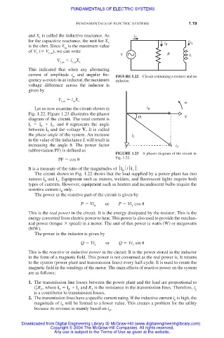
m FIGURE 1.22 Circuit containing a resistor and an
quency exists in an inductor, the maximum inductor.
voltage difference across the inductor is
given by
V i X
L,m m L
Let us now examine the circuit shown in i R
Fig. 1.22. Figure 1.23 illustrates the phasor
diagram of the circuit. The total current is V
i i i , and represents the angle
T R L
between i and the voltage V. It is called
T
the phase angle of the system. An increase i L
in the value of the inductance L will result in
increasing the angle . The power factor i T
(abbreviation PF) is defined as
FIGURE 1.23 A phasor diagram of the circuit in
PF cos Fig. 1.22.
It is a measure of the ratio of the magnitudes of i /i .
R T
The circuit shown in Fig. 1.22 shows that the load supplied by a power plant has two
natures i and i . Equipment such as motors, welders, and fluorescent lights require both
R L
types of currents. However, equipment such as heaters and incandescent bulbs require the
resistive current i only.
R
The power in the resistive part of the circuit is given by
P Vi or P Vi cos
R T
This is the real power in the circuit. It is the energy dissipated by the resistor. This is the
energy converted from electric power to heat. This power is also used to provide the mechan-
ical power (torque speed) in a motor. The unit of this power is watts (W) or megawatts
(MW).
The power in the inductor is given by
Q Vi or Q Vi sin
L T
This is the reactive or inductive power in the circuit. It is the power stored in the inductor
in the form of a magnetic field. This power is not consumed as the real power is. It returns
to the system (power plant and transmission lines) every half-cycle. It is used to create the
magnetic field in the windings of the motor. The main effects of reactive power on the system
are as follows:
1. The transmission line losses between the power plant and the load are proportional to
2
i R , where i i i and R is the resistance in the transmission lines. Therefore, i
T T T R L T L
is a contributor to transmission losses.
2. The transmission lines have a specific current rating. If the inductive current i is high, the
L
magnitude of i will be limited to a lower value. This creates a problem for the utility
R
because its revenue is mainly based on i .
R
Downloaded from Digital Engineering Library @ McGraw-Hill (www.digitalengineeringlibrary.com)
Copyright © 2004 The McGraw-Hill Companies. All rights reserved.
Any use is subject to the Terms of Use as given at the website.