
Page 23 - Electrical Equipment Handbook _ Troubleshooting and Maintenance
P. 23
FUNDAMENTALS OF ELECTRIC SYSTEMS
1.22 CHAPTER ONE
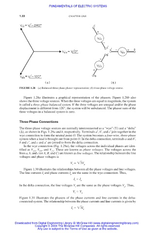
FIGURE 1.28 (a) Balanced three-phase phasor representation; (b) three-phase voltage source.
Figure 1.28a illustrates a graphical representation of the phasors. Figure 1.28b also
shows the three voltage sources. When the three voltages are equal in magnitude, the system
is called a three-phase balanced system. If the three voltages are unequal and/or the phase
displacement is different from 120°, the system will be unbalanced. The phasor sum of the
three voltages in a balanced system is zero.
Three-Phase Connections
The three-phase voltage sources are normally interconnected as a “wye” (Y) and a “delta”
( ), as shown in Figs. 1.29a and b, respectively. Terminals a′, b′, and c′ join together in the
wye connection to form the neutral point O. The system becomes a four-wire, three-phase
system when a lead is brought out from point O. In the delta connection, terminals a and b′,
b and c′, and c and a′ are joined to form the delta connection.
In the wye connection (Fig. 1.29a), the voltages across the individual phases are iden-
tified as V , V , and V . These are known as phase voltages. The voltages across the
a′a b′b c′c
lines a, b, and c (or A, B, and C) are known as line voltages. The relationship between the line
voltages and phase voltages is
V 3 V
l p
Figure 1.30 illustrates the relationships between all the phase voltages and line voltages.
The line currents I and phase currents I are the same in the wye connection. Thus,
l p
I I p
l
In the delta connection, the line voltages V are the same as the phase voltages V . Thus,
l p
V V p
l
Figure 1.31 illustrates the phasors of the phase currents and line currents in the delta-
connected system. The relationship between the phase currents and line currents is given by
I 3 I
l p
Downloaded from Digital Engineering Library @ McGraw-Hill (www.digitalengineeringlibrary.com)
Copyright © 2004 The McGraw-Hill Companies. All rights reserved.
Any use is subject to the Terms of Use as given at the website.