
Page 21 - Electrical Equipment Handbook _ Troubleshooting and Maintenance
P. 21
FUNDAMENTALS OF ELECTRIC SYSTEMS
1.20 CHAPTER ONE
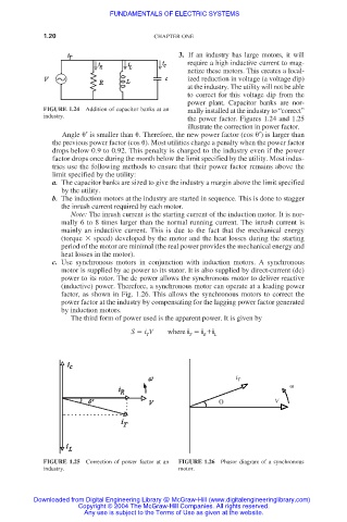
3. If an industry has large motors, it will
require a high inductive current to mag-
netize these motors. This creates a local-
ized reduction in voltage (a voltage dip)
at the industry. The utility will not be able
to correct for this voltage dip from the
power plant. Capacitor banks are nor-
FIGURE 1.24 Addition of capacitor banks at an mally installed at the industry to “correct”
industry.
the power factor. Figures 1.24 and 1.25
illustrate the correction in power factor.
Angle ′ is smaller than . Therefore, the new power factor (cos ′) is larger than
the previous power factor (cos ). Most utilities charge a penalty when the power factor
drops below 0.9 to 0.92. This penalty is charged to the industry even if the power
factor drops once during the month below the limit specified by the utility. Most indus-
tries use the following methods to ensure that their power factor remains above the
limit specified by the utility:
a. The capacitor banks are sized to give the industry a margin above the limit specified
by the utility.
b. The induction motors at the industry are started in sequence. This is done to stagger
the inrush current required by each motor.
Note: The inrush current is the starting current of the induction motor. It is nor-
mally 6 to 8 times larger than the normal running current. The inrush current is
mainly an inductive current. This is due to the fact that the mechanical energy
(torque speed) developed by the motor and the heat losses during the starting
period of the motor are minimal (the real power provides the mechanical energy and
heat losses in the motor).
c. Use synchronous motors in conjunction with induction motors. A synchronous
motor is supplied by ac power to its stator. It is also supplied by direct-current (dc)
power to its rotor. The dc power allows the synchronous motor to deliver reactive
(inductive) power. Therefore, a synchronous motor can operate at a leading power
factor, as shown in Fig. 1.26. This allows the synchronous motors to correct the
power factor at the industry by compensating for the lagging power factor generated
by induction motors.
The third form of power used is the apparent power. It is given by
S i V where i i i L
T
R
T
i T
V
FIGURE 1.25 Correction of power factor at an FIGURE 1.26 Phasor diagram of a synchronous
industry. motor.
Downloaded from Digital Engineering Library @ McGraw-Hill (www.digitalengineeringlibrary.com)
Copyright © 2004 The McGraw-Hill Companies. All rights reserved.
Any use is subject to the Terms of Use as given at the website.