
Page 17 - Electrical Equipment Handbook _ Troubleshooting and Maintenance
P. 17
FUNDAMENTALS OF ELECTRIC SYSTEMS
1.16 CHAPTER ONE
V R R
V R , i R i R
(E = E sin t)
m
(a)
V R
t
0 2
(b)
i (= E /R)
i R R,m m
V R V R,m (= E m )
t
(c)
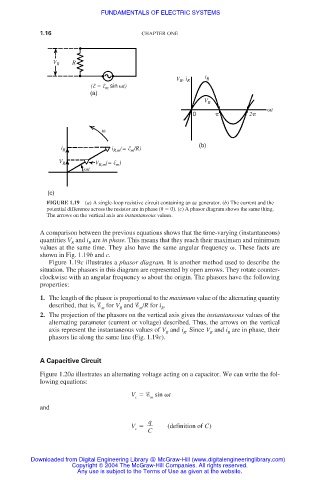
FIGURE 1.19 (a) A single-loop resistive circuit containing an ac generator. (b) The current and the
potential difference across the resistor are in phase ( 0). (c) A phasor diagram shows the same thing.
The arrows on the vertical axis are instantaneous values.
A comparison between the previous equations shows that the time-varying (instantaneous)
quantities V and i are in phase. This means that they reach their maximum and minimum
R R
values at the same time. They also have the same angular frequency . These facts are
shown in Fig. 1.19b and c.
Figure 1.19c illustrates a phasor diagram. It is another method used to describe the
situation. The phasors in this diagram are represented by open arrows. They rotate counter-
clockwise with an angular frequency about the origin. The phasors have the following
properties:
1. The length of the phasor is proportional to the maximum value of the alternating quantity
described, that is, for V and /R for i .
m R m R
2. The projection of the phasors on the vertical axis gives the instantaneous values of the
alternating parameter (current or voltage) described. Thus, the arrows on the vertical
axis represent the instantaneous values of V and i . Since V and i are in phase, their
R R R R
phasors lie along the same line (Fig. 1.19c).
A Capacitive Circuit
Figure 1.20a illustrates an alternating voltage acting on a capacitor. We can write the fol-
lowing equations:
V sin t
c m
and
q
V (definition of C)
c
C
Downloaded from Digital Engineering Library @ McGraw-Hill (www.digitalengineeringlibrary.com)
Copyright © 2004 The McGraw-Hill Companies. All rights reserved.
Any use is subject to the Terms of Use as given at the website.