
Page 16 - Electrical Equipment Handbook _ Troubleshooting and Maintenance
P. 16
FUNDAMENTALS OF ELECTRIC SYSTEMS
FUNDAMENTALS OF ELECTRIC SYSTEMS 1.15
ALTERNATING CURRENT
An alternating current (ac) in a circuit establishes a voltage (emf) that varies with time as
sin t
m
where is the maximum emf and 2 , where is the frequency measured in hertz
m
(Hz). This type of emf is established by an ac generator in a power plant. In North America,
60 Hz. In western Europe and Australia it is 50 Hz. The symbol for a source of
alternating emf is . This device is called an alternating-current generator or an ac gen-
erator. Alternating currents are essential for modern society. Power distribution systems,
radio, television, satellite communication systems, computer systems, etc. would not exist
without alternating voltages and currents.
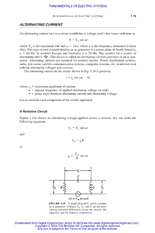
The alternating current in the circuit shown in Fig. 1.18 is given by
i i sin ( t )
m
where i maximum amplitude of current
m
angular frequency of applied alternating voltage (or emf)
phase angle between alternating current and alternating voltage
Let us consider each component of the circuit separately.
A Resistive Circuit
Figure 1.19a shows an alternating voltage applied across a resistor. We can write the
following equations:
V sin t
R m
and
V i R
R R
or
m
i sin t
R
R
FIGURE 1.18 A single-loop RCL circuit contains
an ac generator. Voltages V , V , and V are the time-
L
R
C
varying potential differences across the resistor, the
capacitor, and the inductor, respectively.
Downloaded from Digital Engineering Library @ McGraw-Hill (www.digitalengineeringlibrary.com)
Copyright © 2004 The McGraw-Hill Companies. All rights reserved.
Any use is subject to the Terms of Use as given at the website.