
Page 10 - Electrical Equipment Handbook _ Troubleshooting and Maintenance
P. 10
FUNDAMENTALS OF ELECTRIC SYSTEMS
FUNDAMENTALS OF ELECTRIC SYSTEMS 1.9
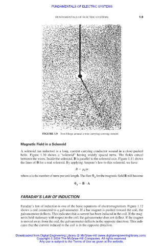
FIGURE 1.9 Iron filings around a wire carrying a strong current.
Magnetic Field in a Solenoid
A solenoid (an inductor) is a long, current-carrying conductor wound in a close-packed
helix. Figure 1.10 shows a “solenoid” having widely spaced turns. The fields cancel
between the wires. Inside the solenoid, B is parallel to the solenoid axis. Figure 1.11 shows
the lines of B for a real solenoid. By applying Ampere’s law to this solenoid, we have
B in
0
where n is the number of turns per unit length. The flux
for the magnetic field B will become
B
B
A
B
FARADAY’S LAW OF INDUCTION
Faraday’s law of induction is one of the basic equations of electromagnetism. Figure 1.12
shows a coil connected to a galvanometer. If a bar magnet is pushed toward the coil, the
galvanometer deflects. This indicates that a current has been induced in the coil. If the mag-
net is held stationary with respect to the coil, the galvanometer does not deflect. If the magnet
is moved away from the coil, the galvanometer deflects in the opposite direction. This indi-
cates that the current induced in the coil is in the opposite direction.
Downloaded from Digital Engineering Library @ McGraw-Hill (www.digitalengineeringlibrary.com)
Copyright © 2004 The McGraw-Hill Companies. All rights reserved.
Any use is subject to the Terms of Use as given at the website.