
Page 203 - Electrical Safety of Low Voltage Systems
P. 203
186 Chapter Eleven
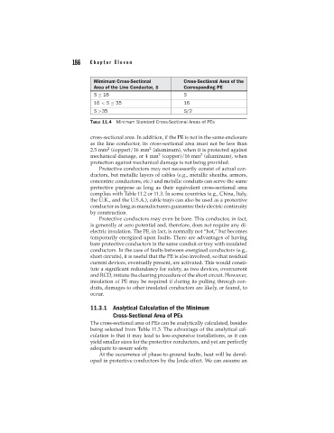
Mimimum Cross-Sectional Cross-Sectional Area of the
Area of the Line Conductor, S Corresponding PE
S ≤ 16 S
16 < S ≤ 35 16
S >35 S/2
TABLE 11.4 Minimum Standard Cross-Sectional Areas of PEs
cross-sectional area. In addition, if the PE is not in the same enclosure
as the line conductor, its cross-sectional area must not be less than
2
2
2.5 mm (copper)/16 mm (aluminum), when it is protected against
2
2
mechanical damage, or 4 mm (copper)/16 mm (aluminum), when
protection against mechanical damage is not being provided.
Protective conductors may not necessarily consist of actual con-
ductors, but metallic layers of cables (e.g., metallic sheaths, armors,
concentric conductors, etc.) and metallic conduits can serve the same
protective purpose as long as their equivalent cross-sectional area
complies with Table 11.2 or 11.3. In some countries (e.g., China, Italy,
the U.K., and the U.S.A.), cable trays can also be used as a protective
conductor as long as manufacturers guarantee their electric continuity
by construction.
Protective conductors may even be bare. This conductor, in fact,
is generally at zero potential and, therefore, does not require any di-
electric insulation. The PE, in fact, is normally not “hot,” but becomes
temporarily energized upon faults. There are advantages of having
bare protective conductors in the same conduit or tray with insulated
conductors. In the case of faults between energized conductors (e.g.,
short circuits), it is useful that the PE is also involved, so that residual
current devices, eventually present, are activated. This would consti-
tute a significant redundancy for safety, as two devices, overcurrent
and RCD, initiate the clearing procedure of the short circuit. However,
insulation of PE may be required if during its pulling through con-
duits, damages to other insulated conductors are likely, or feared, to
occur.
11.3.1 Analytical Calculation of the Minimum
Cross-Sectional Area of PEs
The cross-sectional area of PEs can be analytically calculated, besides
being selected from Table 11.3. The advantage of the analytical cal-
culation is that it may lead to less-expensive installations, as it can
yield smaller sizes for the protective conductors, and yet are perfectly
adequate to assure safety.
At the occurrence of phase-to-ground faults, heat will be devel-
oped in protective conductors by the Joule effect. We can assume an