
Page 208 - Electrical Safety of Low Voltage Systems
P. 208
Earth Electrodes, Protective Conductors 191
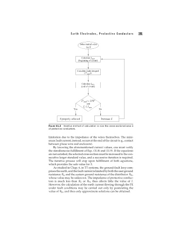
FIGURE 11.3 Iterative method of calculation to size the cross-sectional area S
of protective conductors.
limitation due to the impedance of the wires themselves. The mini-
mum fault current, instead, occurs at the end of the circuit (e.g., contact
between phase wire and enclosure).
By knowing the aforementioned current values, one must verify
the simultaneous fulfillment of Eqs. (11.8) and (11.9). If the equations
arenotsatisfied,theselectedcrosssectionmustbeincreasedtothecon-
secutive larger standard value, and a successive iteration is required.
The iterative process will stop upon fulfillment of both equations,
which provides the safe value for S.
As studied in Chap. 6, in TT systems, the ground-fault loop com-
prisestheearth,andthefaultcurrentislimitedbyboththeuserground
resistance R G and the system ground resistance of the distributor R N ,
whose value may be unknown. The impedance of protective conduc-
tors is much less than R G or R N , thus affects little the value of I.
However, the calculation of the earth current flowing through the PE
under fault conditions may be carried out only by postulating the
value of R N , and thus only approximate solutions can be obtained.