
Page 211 - Electrical Safety of Low Voltage Systems
P. 211
194 Chapter Eleven
no main bonding
Is
Main bonding No main bonding
Supplementary No supplementary
bonding bonding
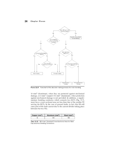
FIGURE 11.6 Flowchart of the decision-making process for main bonding.
2
16 mm (aluminum), when they are protected against mechanical
2
2
damage, or 4 mm (copper)/16 mm (aluminum), when protection
against mechanical damage is not provided. In addition, a supple-
mentary bonding conductor, which connects two ECPs (Fig. 11.7),
must have a cross-sectional area not less than that of the smaller PE
serving the ECPs. In the case of ground faults, in fact, this SB will
carry part of the fault current due to the current divider taking place
between the two PEs.
2
2
2
Copper (mm ) Aluminum (mm ) Steel (mm )
6 16 50
TABLE 11.8 Minimum Standard Cross-Sectional Area for Main
Equipotential Bonding Conductors