
Page 227 - Electrical Safety of Low Voltage Systems
P. 227
210 Chapter Twelve
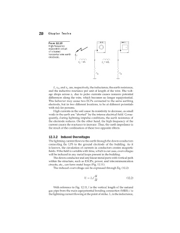
FIGURE 12.10
High-frequency
equivalent circuit
of a buried
horizontal wire earth
electrode.
L, r G , and x L are, respectively, the inductance, the earth resistance,
and the inductive reactance per unit of length of the wire. The volt-
age drops across x L due to pulse currents causes nonzero potential
differences along the wire, which becomes no longer equipotential.
This behavior may cause two ECPs connected to the same earthing
electrode, but in two different locations, to be at different potentials
with risk for persons.
High currents in the soil cause its resistivity to decrease, as small
voids in the earth are “shorted” by the intense electrical field. Conse-
quently, during lightning impulse conditions, the earth resistance of
the electrode reduces. On the other hand, the high frequency of the
current causes the reactance to increase. Thus, the earth impedance is
the result of the combination of these two opposite effects.
12.3.2 Induced Overvoltages
The lightning current flows to the earth through the down-conductors
connecting the LPS to the ground electrode of the building. As it
is known, the circulation of currents in conductors creates magnetic
fields. If the field is variable with time, which is our case, overvoltages
will be induced in any metal loops present in the building.
The down-conductor and any linear metal parts with vertical path
within the structure, such as EXCPs, power, and telecommunication
circuits, etc., can form metal loops (Fig. 12.11).
The induced overvoltage can be expressed through Eq. (12.2):
di
V i = L l l (12.2)
dt
With reference to Fig. 12.11, l is the vertical length of the natural
gas pipe from the main equipotential bonding connection (MEB); i is
the lightning current flowing at the point of strike. L l is the inductance,