
Page 222 - Electrical Safety of Low Voltage Systems
P. 222
Safety Against Overvoltages 205
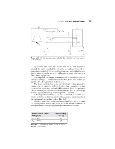
FIGURE 12.4 Neutral conductor connected to the substation earthing system
in TT systems.
Upon high-side faults, the neutral will reach, with respect to
ground, the earth potential V G , while the low-voltage ECPs will re-
main at zero potential. Consequently, a temporary potential difference
V S2 , of maximum value V ph + V G , will appear across the insulation of
low-voltage equipment.
To limit possible damages to the insulation, permissible values for
the stress voltage, as a function of its duration, have been elaborated
by IEC 60364-4-44, as shown in Table 12.1.
The disconnecting time is the time the high-voltage protective
device takes to clear the fault. A clearing time exceeding5smay
be typical of inductively grounded HV systems. Table 12.1 provides
the criterion to properly rate the insulation-to-ground of low-voltage
systems against temporary overvoltages in TT systems.
If the inequalities of Table 12.1 cannot be fulfilled, the neutral con-
ductor of the low-voltage system must be grounded independently of
the substation’s grounding system (Fig. 12.5).
Also in this case, the maximum stress voltage V S1 = V ph + V G must
be interrupted in a time compatible with the minimum insulation
rating of the low-voltage equipment present in the substation.
Permissible LV Stress Disconnecting
Voltage (V) Time (s)
V ph + 250 >5
V ph + 1200 ≤5
TABLE 12.1 Permissible Values for the LV Stress
Voltage in TT Systems