
Page 224 - Electrical Safety of Low Voltage Systems
P. 224
Safety Against Overvoltages 207
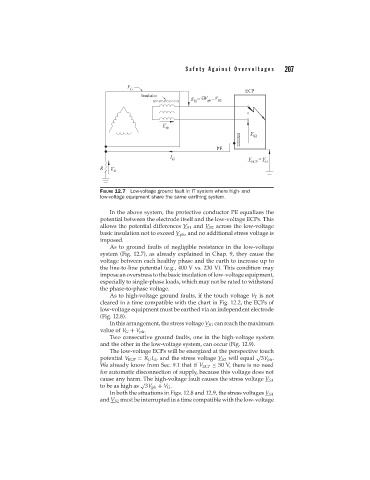
FIGURE 12.7 Low-voltage ground fault in IT system where high- and
low-voltage equipment share the same earthing system.
In the above system, the protective conductor PE equalizes the
potential between the electrode itself and the low-voltage ECPs. This
allows the potential differences V S1 and V S2 across the low-voltage
basic insulation not to exceed V ph , and no additional stress voltage is
imposed.
As to ground faults of negligible resistance in the low-voltage
system (Fig. 12.7), as already explained in Chap. 9, they cause the
voltage between each healthy phase and the earth to increase up to
the line-to-line potential (e.g., 400 V vs. 230 V). This condition may
impose an overstress to the basic insulation of low-voltage equipment,
especially to single-phase loads, which may not be rated to withstand
the phase-to-phase voltage.
As to high-voltage ground faults, if the touch voltage V T is not
cleared in a time compatible with the chart in Fig. 12.2, the ECPs of
low-voltage equipment must be earthed via an independent electrode
(Fig. 12.8).
In this arrangement, the stress voltage V S1 can reach the maximum
value of V G + V ph .
Two consecutive ground faults, one in the high-voltage system
and the other in the low-voltage system, can occur (Fig. 12.9).
The low-voltage ECPs will be energized at the perspective touch
√
potential V ECP = R U I d , and the stress voltage V S2 will equal 3V ph .
We already know from Sec. 9.1 that if V ECP ≤ 50 V, there is no need
for automatic disconnection of supply, because this voltage does not
cause any harm. The high-voltage fault causes the stress voltage V S1
√
to be as high as 3V ph + V G .
In both the situations in Figs. 12.8 and 12.9, the stress voltages V S1
and V S2 must be interrupted in a time compatible with the low-voltage