Page 34 - Electrical Safety of Low Voltage Systems
P. 34

Fundamentals of Electrical Safety      17


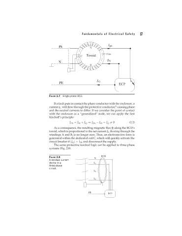
                                  FIGURE 2.7 Single-phase RCD.

                                     If a fault puts in contact the phase conductor with the enclosure, a
                                                                              8
                                  current I G will flow through the protective conductor, causing phase
                                  and the neutral currents to differ. If we consider the point of contact
                                  with the enclosure as a “generalized” node, we can apply the first
                                  Kirchoff’s principle:
                                                I  = I + I ⇒ I    − I  = I  = 0         (2.2)
                                                 Ph   N   G     Ph   N   G
                                     As a consequence, the resulting magnetic flux   along the RCD’s
                                  toroid, which is proportional to the net current I G flowing through the
                                  windings A and B, is no longer zero. Thus, an electromotive force is
                                  generated within the dedicated coil C, which will quickly activate the
                                  circuit breaker if |I | > I dn and disconnect the supply.
                                                  G
                                     The same protective residual logic can be applied to three-phase
                                  systems (Fig. 2.8).


                                  FIGURE 2.8
                                  A residual current
                                  device in a
                                  three-phase
                                  circuit.
   29   30   31   32   33   34   35   36   37   38   39