
Page 38 - Electrical Safety of Low Voltage Systems
P. 38
Fundamentals of Electrical Safety 21
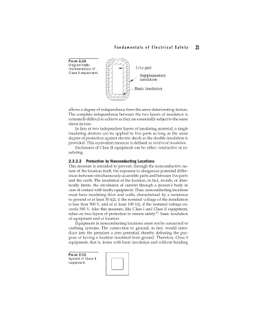
FIGURE 2.10
Diagrammatic
representation of
Class II equipment.
allows a degree of independence from the same deteriorating factors.
The complete independence between the two layers of insulation is
extremely difficult to achieve as they are essentially subject to the same
stress factors.
In lieu of two independent layers of insulating material, a single
insulating stratum can be applied to live parts as long as the same
degree of protection against electric shock as the double insulation is
provided. This equivalent measure is defined as reinforced insulation.
Enclosures of Class II equipment can be either conductive or in-
sulating.
2.3.2.2 Protection by Nonconducting Locations
This measure is intended to prevent, through the nonconductive na-
ture of the location itself, the exposure to dangerous potential differ-
ences between simultaneously accessible parts and between live parts
and the earth. The insulation of the location, in fact, avoids, or dras-
tically limits, the circulation of current through a person’s body in
case of contact with faulty equipment. Thus, nonconducting locations
must have insulating floor and walls, characterized by a resistance
to ground of at least 50 k , if the nominal voltage of the installation
is less than 500 V, and of at least 100 k , if the nominal voltage ex-
ceeds 500 V. Also this measure, like Class I and Class II equipment,
10
relies on two layers of protection to ensure safety : basic insulation
of equipment and of location.
Equipment in nonconducting locations must not be connected to
earthing systems. The connection to ground, in fact, would intro-
duce into the premises a zero potential, thereby defeating the pur-
pose of having a location insulated from ground. Therefore, Class 0
equipment, that is, items with basic insulation and without bonding
FIGURE 2.11
Symbol of Class II
equipment.