
Page 55 - Electrical Safety of Low Voltage Systems
P. 55
38 Chapter Three
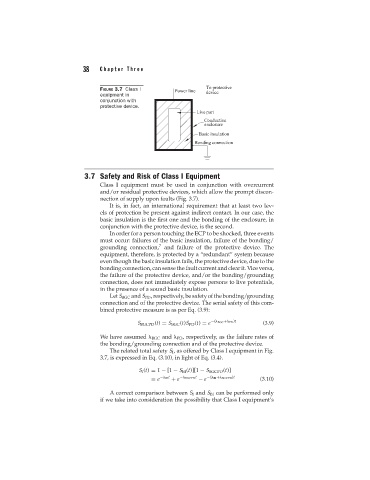
FIGURE 3.7 Class I
equipment in
conjunction with
protective device.
3.7 Safety and Risk of Class I Equipment
Class I equipment must be used in conjunction with overcurrent
and/or residual protective devices, which allow the prompt discon-
nection of supply upon faults (Fig. 3.7).
It is, in fact, an international requirement that at least two lev-
els of protection be present against indirect contact. In our case, the
basic insulation is the first one and the bonding of the enclosure, in
conjunction with the protective device, is the second.
In order for a person touching the ECP to be shocked, three events
must occur: failures of the basic insulation, failure of the bonding/
7
grounding connection, and failure of the protective device. The
equipment, therefore, is protected by a “redundant” system because
even though the basic insulation fails, the protective device, due to the
bonding connection, can sense the fault current and clear it. Vice versa,
the failure of the protective device, and/or the bonding/grounding
connection, does not immediately expose persons to live potentials,
in the presence of a sound basic insulation.
Let S BGC and S PD , respectively, be safety of the bonding/grounding
connection and of the protective device. The serial safety of this com-
bined protective measure is as per Eq. (3.9):
S BGCPD (t) = S BGC (t)S PD (t) = e −( BGC + PD )t (3.9)
We have assumed BGC and PD , respectively, as the failure rates of
the bonding/grounding connection and of the protective device.
The related total safety S I , as offered by Class I equipment in Fig.
3.7, is expressed in Eq. (3.10), in light of Eq. (3.4).
S I (t) = 1 − [1 − S BI (t)][1 − S BGCPD (t)]
= e − BI t + e − BGCPD t − e −( BI + BGCPD )t (3.10)
A correct comparison between S I and S BI can be performed only
if we take into consideration the possibility that Class I equipment’s