
Page 56 - Electrical Safety of Low Voltage Systems
P. 56
Mathematical Principles of Electrical Safety 39
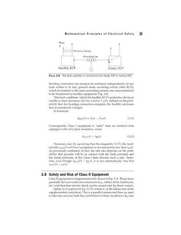
FIGURE 3.8 The fault potential is transferred from faulty ECP to healthy ECP .
bonding connection can energize its enclosure independently of any
fault within it. In fact, ground faults occurring within other ECPs,
which are bonded to the same grounding system, can cause potentials
to be transferred to healthy equipment (Fig. 3.8).
This fault condition, which the healthy ECP’s protective device is
unable to clear, decreases S I (t) by a factor F TP (t), defined as the prob-
ability that the bonding connection energizes the healthy enclosure
due to transferred voltages.
In formulas:
S ITOT (t) = S I (t) − F TP (t) (3.11)
Consequently, Class I equipment is “safer” than an electrical item
equipped with only basic insulation, when
S ITOT (t) > S BI (t) (3.12)
However, even by assuming true the inequality (3.12), the resid-
ual risk r ITOT (t) of Class I equipment is not necessarily less than r BI (t).
As previously explained, in fact, the risk also depends on the prob-
ability that persons will be in contact with the fault potential and
the metal enclosure of the Class I item elevates such a risk. There-
fore, even though S ITOT (t) > S BI (t), it is not automatically true that
r ITOT (t) < r BI (t).
3.8 Safety and Risk of Class II Equipment
Class II equipment is diagrammatically shown in Fig. 2.11. These items
generally have no conductive enclosure (e.g., cables, drills, hairdryers,
etc.) and therefore electric shock can be caused only by direct contact.
Safety S II (t) is given by Eq. (3.13), where SI is the failure rate of the
supplementary insulation. This is a parallel system and thus we need
to take into account both the contribution of basic insulation (S BI ) and