
Page 57 - Electrical Safety of Low Voltage Systems
P. 57
40 Chapter Three
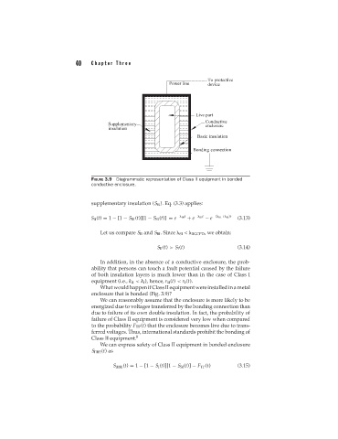
FIGURE 3.9 Diagrammatic representation of Class II equipment in bonded
conductive enclosure.
supplementary insulation (S SI ). Eq. (3.3) applies:
S II (t) = 1 − [1 − S BI (t)][1 − S SI (t)] = e − BI t + e − SI t − e −( BI + SI )t (3.13)
Let us compare S II and S BI . Since SI < BGCPD , we obtain:
S II (t) > S I (t) (3.14)
In addition, in the absence of a conductive enclosure, the prob-
ability that persons can touch a fault potential caused by the failure
of both insulation layers is much lower than in the case of Class I
equipment (i.e., k II < k I ), hence, r II (t) < r I (t).
What would happen if Class II equipment were installed in a metal
enclosure that is bonded (Fig. 3.9)?
We can reasonably assume that the enclosure is more likely to be
energized due to voltages transferred by the bonding connection than
due to failure of its own double insulation. In fact, the probability of
failure of Class II equipment is considered very low when compared
to the probability F TP (t) that the enclosure becomes live due to trans-
ferred voltages. Thus, international standards prohibit the bonding of
Class II equipment. 8
We can express safety of Class II equipment in bonded enclosure
S IIBE (t)as
S IIBE (t) = 1 − [1 − S I (t)][1 − S SI (t)] − F TP (t) (3.15)