
Page 413 - Electromagnetics
P. 413
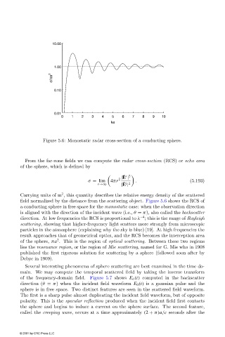
10.00


                                      1.00
                                     σ/πa 2


                                      0.10


                                      0.01
                                         0   1   2   3    4   5   6   7    8   9   10
                                                             ka


                                 Figure 5.6: Monostatic radar cross-section of a conducting sphere.


                          From the far-zone fields we can compute the radar cross-section (RCS) or echo area
                        of the sphere, which is defined by


      ˜ s 2
                                                                  |E |
                                                                 2
                                                    σ = lim  4πr        .                     (5.193)
                                                                   ˜ i 2
                                                        r→∞       |E |
                                         2
                        Carrying units of m , this quantity describes the relative energy density of the scattered
                        field normalized by the distance from the scattering object. Figure 5.6 shows the RCS of
                        a conducting sphere in free space for the monostatic case: when the observation direction
                        is aligned with the direction of the incident wave (i.e., θ = π), also called the backscatter
                                                                          −4
                        direction. At lowfrequencies the RCS is proportional to λ ; this is the range of Rayleigh
                        scattering, showing that higher-frequency light scatters more strongly from microscopic
                        particles in the atmosphere (explaining why the sky is blue) [19]. At high frequencies the
                        result approaches that of geometrical optics, and the RCS becomes the interception area
                                       2
                        of the sphere, πa . This is the region of optical scattering. Between these two regions
                        lies the resonance region, or the region of Mie scattering, named for G. Mie who in 1908
                        published the first rigorous solution for scattering by a sphere (followed soon after by
                        Debye in 1909).
                          Several interesting phenomena of sphere scattering are best examined in the time do-
                        main. We may compute the temporal scattered field by taking the inverse transform
                        of the frequency-domain field. Figure 5.7 shows  E θ (t) computed in the backscatter
                        direction (θ = π) when the incident field waveform E 0 (t) is a gaussian pulse and the
                        sphere is in free space. Two distinct features are seen in the scattered field waveform.
                        The first is a sharp pulse almost duplicating the incident field waveform, but of opposite
                        polarity. This is the specular reflection produced when the incident field first contacts
                        the sphere and begins to induce a current on the sphere surface. The second feature,
                        called the creeping wave, occurs at a time approximately (2 + π)a/c seconds after the


                        © 2001 by CRC Press LLC