
Page 167 - Electromechanical Devices and Components Illustrated Sourcebook
P. 167
Chapter 7 Heating 129
Coil
Terminal
Component to
be Heated Eddy Currents
Terminal
RF Power Supply
Figure 7-6 Induction Heating Schematic
Open Element for
Model Airplane Engines
heating occurs. Figure 7-6 shows schematic representation of
an induction heating system. The frequency of the AC signal
is generally between 22,000 and 100,000 Hz. The frequency
is dependent on the geometry of the part and the type of ther-
mal patterns that are required.
Figure 7-7 shows a typical induction coil for heating a sec-
tion of tubing. The coils are normally constructed from cop-
per tube so that continuous cooling can be applied during the
Shrouded Element for
Industrial Engines operation. Electrical terminals are simply tabs of copper silver
soldered to the coil ends.
Figure 7-4 Commercial Glow Plugs
Terminals Part Being
Heated
Heat-Affected
Inductive Heating Zone
Metal components can be readily heated by manipulating the Water Feed Coil
eddy currents that naturally form when the piece is exposed to
an AC signal. This is a common practice in industry and is fre-
quently used in forging and heat-treating operations. The
basic concept is rather simple. The part that needs to be
heated is placed into a coil and a high frequency signal is fed
to the coil. Eddy currents are set up in the piece and resistive Figure 7-7 Induction Heating Element
10
9
22 AWG
8
7
24 AWG
6
5
4
28 AWG
3
Ohms Per Foot
2
1
0
°F 800 900 1000 1100 1200 1300 1400 1500 1600 1700 1800 1900 2000
°C 425 480 550 590 650 700 750 820 875 930 980 1040 1100
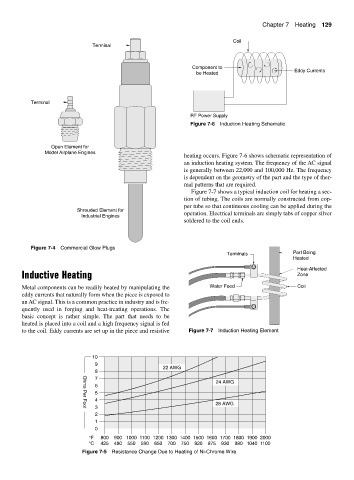
Figure 7-5 Resistance Change Due to Heating of Ni-Chrome Wire