
Page 180 - Electromechanical Devices and Components Illustrated Sourcebook
P. 180
142 Electromechanical Devices & Components Illustrated Sourcebook
circuit. Grounds and grounding methodologies are the base
circuit for virtually all electrical controls, electromechanical
Switch MOV devices, and equipment. When working with electrical equip-
ment a good rule of thumb is “when in doubt, ground.” A good
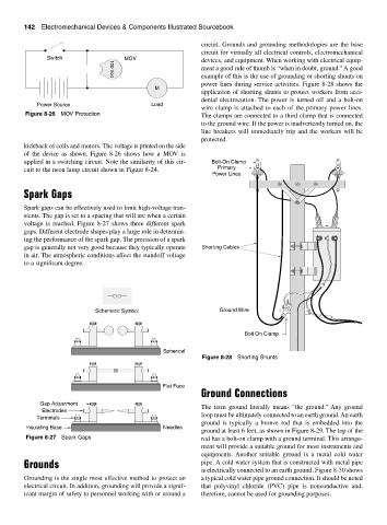
example of this is the use of grounding or shorting shunts on
100 Volt
power lines during service activities. Figure 8-28 shows the
M
application of shorting shunts to protect workers from acci-
dental electrocution. The power is turned off and a bolt-on
Power Source Load
wire clamp is attached to each of the primary power lines.
Figure 8-26 MOV Protection The clamps are connected to a third clamp that is connected
to the ground wire. If the power is inadvertently turned on, the
line breakers will immediately trip and the workers will be
protected.
kickback of coils and motors. The voltage is printed on the side
of the device as shown. Figure 8-26 shows how a MOV is
applied in a switching circuit. Note the similarity of this cir- Bolt-On Clamp
cuit to the neon lamp circuit shown in Figure 8-24. Primary
Power Lines
Spark Gaps
Spark gaps can be effectively used to limit high-voltage tran-
sients. The gap is set to a spacing that will arc when a certain
voltage is reached. Figure 8-27 shows three different spark
gaps. Different electrode shapes play a large role in determin-
ing the performance of the spark gap. The precision of a spark
gap is generally not very good because they typically operate Shorting Cables
in air. The atmospheric conditions affect the standoff voltage
to a significant degree.
Schematic Symbol Ground Wire
Bolt On Clamp
Spherical
Figure 8-28 Shorting Shunts
Flat Face
Ground Connections
Gap Adjustment
The term ground literally means “the ground.” Any ground
Electrodes
loop must be ultimately connected to an earth ground. An earth
Terminals
ground is typically a bronze rod that is embedded into the
Insulating Base Needles
ground at least 6 feet, as shown in Figure 8-29. The top of the
Figure 8-27 Spark Gaps rod has a bolt-on clamp with a ground terminal. This arrange-
ment will provide a suitable ground for most instruments and
equipments. Another suitable ground is a metal cold water
Grounds pipe. A cold water system that is constructed with metal pipe
is electrically connected to an earth ground. Figure 8-30 shows
Grounding is the single most effective method to protect an a typical cold water pipe ground connection. It should be noted
electrical circuit. In addition, grounding will provide a signif- that polyvinyl chloride (PVC) pipe is nonconductive and,
icant margin of safety to personnel working with or around a therefore, cannot be used for grounding purposes.