
Page 178 - Electromechanical Devices and Components Illustrated Sourcebook
P. 178
140 Electromechanical Devices & Components Illustrated Sourcebook
Magnetic Arc Suppression Heat
Smaller applications, such as motor contactors, will often
incorporate magnetic arc suppression. In this arrangement the
arc is exposed to a perpendicular magnetic field, as shown in Opened
(Tripped)
Figure 8-16. As the arc forms, the magnetic field forces it into Open Contacts
a long, curved path and the arc extinguishes.
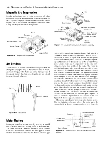
Axle Housing Induction Coil (Heater)
Axle
Serrated Wheel Solder Head
Reset Button
Arc
Motor Terminals
Contacts Housing Mount
Switch Terminals
Terminals
Ratchet Rack
Closed Contacts
Trip Spring Closed
Magnetic Blowout Coil
(Operate)
Figure 8-18 Inductive Heating Motor Protection Assembly
Magnet Frame
Magnetic Field that we will discuss is the inductive heater. Each pole of a
Figure 8-16 Magnetic Arc Suppression commercial motor starter is equipped with a thermal kick-out
mechanism, as shown in Figure 8-18. The heart of the system
is the inductive heater, which is matched to the operating volt-
age and horsepower of the motor. The heater is connected in
Arc Dividers series with the motor and in conjunction with the core, mim-
icking the basic heat profile of the motor. The heater is
An arc divider is a series of nonconductive plates that are installed in close proximity to an axle mounted within a hous-
arranged in close proximity to the formation area of the arc, ing (the core). The head of the axle and housing are joined
as shown in Figure 8-17. As the arc forms, the heat forces it with a low-temperature solder joint. The opposite end of the
to rise and it enters the plate array. Once the arc has entered axle has a serrated wheel. A ratcheted rack engages the wheel
the array, the path is broken. and is designed to close and hold the contact set. The oppo-
site end of the ratchet rack has a reset button. Under normal
conditions the inductive heater produces very little heat in the
core and the motor circuit operates without incident. Under
overload conditions the heater induces enough heat to melt the
Plates solder joint, allowing the axle and serrated wheel to freely
Arc
rotate. At this point, the trip spring forces the ratchet rack back
and the contacts open. The contacts are wired in series to the
contactor coil and when open, the contactor opens. Figure 8-19
shows a schematic representation of a motor starter and
Contacts
Figure 8-20 shows a typical commercial motor starter.
The second type of motor protection is the thermal heater.
Like the inductive unit, each pole of the motor starter is
equipped with a thermal kick-out mechanism, as shown in
Figure 8-17 Arc Divider Overload Protection
Contactor
Induction Coils
(Heaters)
220/480 VAC
Motor Heaters Three-Phase
Switch
C
Protecting induction motors generally requires a special M
type of system based on a heating profile as well as current. Coil Jumper Motor
Reset Button
The motor should be connected through a set of standard Control Signal
fuses and a motor starter. There are two basic types of heaters Figure 8-19 Schematic for a Motor Starter with Inductive
used on motor starters, inductive and thermal. The first type Heaters