
Page 181 - Electromechanical Devices and Components Illustrated Sourcebook
P. 181
Chapter 8 Circuit Protection 143
Ground Wire
Hand
Rod Clamp
Ground Terminal
Clamp Bolt Plate
Ground Rod
Rod
C-Clamp
Large Pipe
Soil Cable
6 Foot (Min.)
Rod Small Pipe
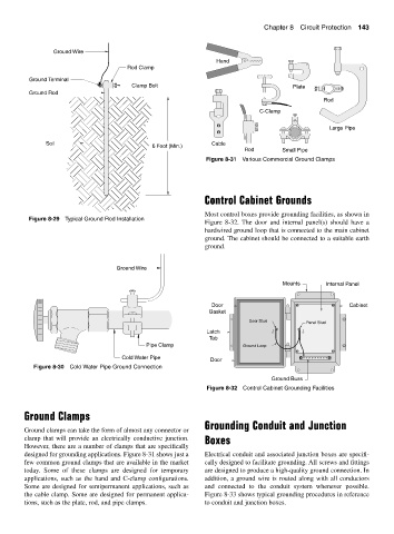
Figure 8-31 Various Commercial Ground Clamps
Control Cabinet Grounds
Most control boxes provide grounding facilities, as shown in
Figure 8-29 Typical Ground Rod Installation
Figure 8-32. The door and internal panel(s) should have a
hardwired ground loop that is connected to the main cabinet
ground. The cabinet should be connected to a suitable earth
ground.
Ground Wire
Mounts Internal Panel
Door Cabinet
Gasket
Door Stud Panel Stud
Latch
Tab
Pipe Clamp Ground Loop
Cold Water Pipe
Door
Figure 8-30 Cold Water Pipe Ground Connection
Ground Buss
Figure 8-32 Control Cabinet Grounding Facilities
Ground Clamps
Grounding Conduit and Junction
Ground clamps can take the form of almost any connector or
clamp that will provide an electrically conductive junction. Boxes
However, there are a number of clamps that are specifically
designed for grounding applications. Figure 8-31 shows just a Electrical conduit and associated junction boxes are specifi-
few common ground clamps that are available in the market cally designed to facilitate grounding. All screws and fittings
today. Some of these clamps are designed for temporary are designed to produce a high-quality ground connection. In
applications, such as the hand and C-clamp configurations. addition, a ground wire is routed along with all conductors
Some are designed for semipermanent applications, such as and connected to the conduit system whenever possible.
the cable clamp. Some are designed for permanent applica- Figure 8-33 shows typical grounding procedures in reference
tions, such as the plate, rod, and pipe clamps. to conduit and junction boxes.