Page 179 - Electromechanical Devices and Components Illustrated Sourcebook
P. 179

Chapter 8  Circuit Protection 141

                                    Contactor                                                  Overload Protection
                                                                             Contactor
                                                                                                 Heaters
                                              Reset Button
                                                               220/480 VAC
                                                Heaters        Three-Phase
            Coil
          Terminals                                                                  C
                                                 Overload                                                  M
                                                 Protector
                                                                             Coil      Jumper     Switch  Motor
             Jumper                                               Control Signal
                                                   Base
                                                               Figure 8-22 Schematic for a Motor Starter with Thermal
                                                               Heaters
                  Switch Terminals
          Figure 8-20 Commercial Motor Starter


                                                               Power Input               Contactor
                                         Motor Terminals                                         Heaters


                                                                                                   Motor Terminals
           Contacts                        Heating Element
                        Bimetal Strip
            Closed
           (Operate)                                                                                 Coil Terminals
                           Switch Terminals                    Figure 8-23 Commercial Motor Starter with Integral Thermal
                                                               Heater Protection


                                            Heat
             Open
          (Over Load)
                                                                      Switch           Neon Lamp
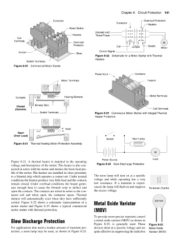
          Figure 8-21 Thermal Heating Motor Protection Assembly

                                                                                                      M

                                                                    Power Source                     Load
        Figure 8-21. A thermal heater is matched to the operating
                                                                Figure 8-24 Glow Discharge Protection
        voltage and horsepower of the motor. This heater is also con-
        nected in series with the motor and mimics the basic heat pro-
        file of the motor. The heaters are installed in close proximity
        to a bimetal strip which operates a contact set. Under normal  The neon lamp will turn on at a specific
        conditions the heaters produce very little heat and the contacts  voltage and while operating has a very
        remain closed. Under overload conditions the heater gener-  low resistance. If a transient is experi-
        ates enough heat to cause the bimetal strip to deflect and  enced, the lamp will flash on and suppress  Schematic Symbol
        open the contacts. The contacts are wired in series to the con-  the excess voltage.
        tactor coil and when open, the contactor opens.  Thermal
        starters will automatically reset when they have sufficiently
                                                                                                      250 Volt
        cooled. Figure 8-22 shows a schematic representation of a  Metal Oxide Varistor
        motor starter and Figure 8-23 shows a typical commercial
        motor starter with thermal protection.                (MOV)
                                                              To provide more precise transient control
        Glow Discharge Protection                             a metal oxide varistor (MOV) as shown in
                                                              Figure 8-25, is generally used.  These  Figure 8-25
        For applications that need a modest amount of transient pro-  devices short at a specific voltage and are  Metal Oxide
        tection, a neon lamp may be used, as shown in Figure 8-24.  quite effective in suppressing the inductive  Varistor (MOV)
   174   175   176   177   178   179   180   181   182   183   184