
Page 216 - Electromechanical Devices and Components Illustrated Sourcebook
P. 216
178 Electromechanical Devices & Components Illustrated Sourcebook
Color Coded Guide Lines lines are numbered. Written instructions can be provided to
3/8 inch Wooden Dowel Pin the technician for setting any given wiring harness design.
Fixture Number Plywood Base
Cutting and Stripping Wire
A-147-B
Cutting wire is a simple process aided by a variety of cutters
that are commonly available. Figure 10-31 shows a few wire
cutters that may be found in any tool box or electrical shop.
The side cutter is the anchor of the wire cutting world. These
tools are available in very small units for delicate work
through large, heavy duty units for cutting thick conductors.
End cutters are similar to side cutters, except that the cutting
edges are oriented on the end. These provide easy access for
locations that have limited surrounding clearance. A wire cut-
ting element is routinely added to all sorts of pliers. The most
Figure 10-29 Wiring Harness Fixture
common are the lineman and needle nose pliers. For cutting
heavy wires and cables, special hook nose cutters are used.
These prevent the cable from slipping out of the jaws during
cutting operations.
For building wire harnesses on a production basis, a sim- To connect a conductor it is usually necessary to strip off
ple fixture can be constructed, as shown in Figure 10-29. A the insulation. This is generally done by cutting or scoring the
board is laid out with a series of wooden dowel pine and col- insulation and then pulling off the end piece. Larger conduc-
ored guidelines are drawn on the board to guide the construc- tors can be scored with an ordinary razor blade knife, then
tion process. Each board is given a fixture number and can be pulled off by hand. Great care should be taken to avoid dam-
easily stored when not in use. aging the conductor when stripping wire with this method.
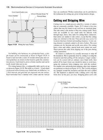
For wiring harness labs, a configurable table can be set up For smaller wire and production stripping, plier type strippers
as shown in Figure 10-30. The table is a 4 inch 8 inch sheet are preferred, as shown in Figure 10-32. The V-notch strippers
of plywood with a Formica top. Guide holes are drilled at 1 or are clamped around the insulation and then the end is pulled
2 inch intervals and grid lines are engraved onto the surface. off. The diameter is adjusted with a sliding screw stop that
Each horizontal line is labeled with a letter and the vertical limits how far the jaws can close. Stripping pliers work with
1/4 inch Guide Holes
741 Places
Grid Lines
Side Scale 4 feet × 8 feet Formica Covered Top
S
R
Q
P
O
N
M
L
K
J
I
H
G
F
E
D
C
B
A
1 2 3 4 5 6 7 8 9 10 11 12 13 14 15 16 17 18 19 20 21 22 23 24 25 26 27 28 29 30 31 32 33 34 35 36 37 38 39
Base Scale
Figure 10-30 Wiring Harness Table