
Page 222 - Electromechanical Devices and Components Illustrated Sourcebook
P. 222
184 Electromechanical Devices & Components Illustrated Sourcebook
Wire Groove
Joist
Wire
Ceramic Insulator
Insulator
Figure 10-50 Ceramic Feedthrough Insulator Drip Ring
Glass Insulator
Metal Stud
Wire Groove
Drip Ring
Load Spreader
Wooden Post
Washer
Nut
Figure 10-51 Glass Insulator Figure 10-52 Modern Ceramic Pole Insulator
and are now sought after by antique collectors. Figure 10-51 Wire Groove
shows a typical glass insulator of the early twentieth century.
The transmission line was aligned with the wire groove and a
second piece of wire was wrapped onto the line, around the Ceramic Insulator
opposite side of the groove and back around the line. These
insulators were typically mounted on a threaded wooden post
that was either nailed onto or driven into the pole.
Modern pole insulators do not differ much from their glass
predecessors. Figure 10-52 shows a typical ceramic pole insu-
lator. In order to support higher cable weights, the wire
groove is on the top of the insulator and is laced onto the unit
with a length of solid wire. These insulators are designed to
screw directly onto a steel post, as shown. The steel post is
generally inserted through a through hole in the cross beam
and a pair of load spreaders, washer, and nut are used to
secure the assembly.
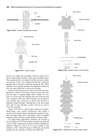
Figure 10-53 shows a typical high-voltage pole insulator.
High-voltage, cross country transmission lines require a
greater level of isolation than a standard pole insulator can pro-
vide. The high-voltage unit is essentially a stack of standard
insulators used to provide a greater stand-off voltage rating. Threaded Stud
For high-tension applications, insulators are stacked as
shown in Figure 10-54. Each insulator assembly can stand off
a given voltage. Hanging ten insulators together multiplies the Washer
stand-off voltage by a factor of 10. As an example, if four
insulators, with a stand-off voltage of 7500 each, are stacked Nut
together then the assembly can stand off 30,000 volts. Figure 10-53 Ridged Mount, High-Voltage Insulator