
Page 332 - Electromechanical Devices and Components Illustrated Sourcebook
P. 332
294 Electromechanical Devices & Components Illustrated Sourcebook
C 1 C 2 C 3
T 1 T 2
R 2 R 3
J (Input) R 1 R 4 P 1
1
(Output)
− + − +
B 2 B 3
− +
S 1
B 1
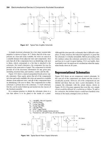
Figure 18-7 Typical Tube Amplifier Schematic
A simple electronic schematic for a two-stage vacuum tube Although this does provide a schematic that is difficult to mis-
amplifier is shown in Figure 18-7. Notice that all of the com- place, in many instances the reduction required is so great that
ponents are clear and easily readable, the wires are spaced at the schematic is virtually unreadable. Before proceeding with
a suitable distance from adjacent wires and components. Also this method, reduce the schematic and print it out. Get it dirty
note that all of the components have an identifying code next and then try to read it in poor lighting. If it’s not legible, then
to them, which corresponds to a list that is attached to the it probably won’t be much use to a technician when the equip-
schematic. For small schematics, the component list may be ment breaks down in 20 years.
printed on the same piece of paper. The component list should
provide all of the necessary information for any given part,
including electrical data, part number, vendor, and the like. Representational Schematics
Figure 18-8 shows a typical unregulated bench power sup-
ply schematic. Once again, notice that all of the components Figure 18-9 shows an air compressor control schematic. In
are clear and easily readable, the wires are spaced at a suitable this case all of the components are shown and the circuit is
distance from adjacent wires, and all of the components have electrically accurate. However, all of the components are not
an identifying code next to them. The component list on this labeled and those that are, have a poor description. If you
schematic is printed above the schematic. A small schematic compare the schematic with the actual chassis, shown in
like this can be easily folded up and tucked into the chassis of Figure 18-10, it becomes apparent that even this very simple
the finished assembly. circuit would be difficult for a technician to follow. To add to
It is common practice to shrink the schematic down to a the confusion, the finished chassis would have bundled wires
size that allows it to be glued to the inside of a panel. instead of the neatly arranged wires as shown.
C 1 100-MFD, 100-volt Capacitor
D 1-4 400-PIV Diode
F 1 5-amp Type MDL
F 2 8-amp Type MDL
P 1 120-VAC Plug
S 1 SPST Toggle Switch
0- to 120-VAC Variable Autotransformer
T 1
T 2 Transformer, 120-volt Primary, 50-volt Secondary
+
S 1
+
C 1 DC Output
F 2 −
−
D 1-4
F 1
P 1
120 VAC T 1 M 1
AC Output
T 2
Figure 18-8 Typical Bench Power Supply Schematic