
Page 333 - Electromechanical Devices and Components Illustrated Sourcebook
P. 333
Chapter 18 Electrical Schematics 295
Motor Controller
480 VAC 3 Phase
C L Power
M
120 V Motor
Control
Relay
Fault L
On/Off/Auto
Switch Over Pressure
Low Oil Pressure
T Over Temperature
Pressure Switch
Delay Off Emergency Stop
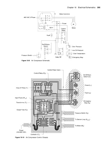
Figure 18-9 Air Compressor Schematic
Control Panel Cable
Control Relay (R )
2
On/Off/Auto
)
Switch (S 1
Power (L )
1
2.5
2.0 3.0
1.5 3.5
Delay Off Relay (R 1 ) 1.0 4.0 10 Amp DC
.5 4.5 120 VAC Coil
0 5.0
Seconds
Fault (L )
2
Input Fuses (R 1,2 )
Emergency
Transformer (T ) Stop (S 6 )
1
115/120 VAC
Output Fuse (F )
240/480 VAC
3
Pressure Switch (S )
2
)
To Sensor Loop (S 3,4,5
MOTOR
STARTER RESET
120 VAC COIL
)
To Motor (M 1
Power
(240/480 VAC)
Contactor (C )
1
Figure 18-10 Air Compressor Control Chassis