Page 336 - Electromechanical Devices and Components Illustrated Sourcebook
P. 336

298 Electromechanical Devices & Components Illustrated Sourcebook

                                  C 1

                                               T 1                             T
                                                       C 2                      2     C 3
                                          4    5                         4    5
                                  R 1  3          6              R 3  3          6


                                       2          7    R 2            2          7    R 4
                   J 1  (Input)
                                          1    8                         1    8


                                              −
                                −                                          −
                            B 2                     B 1                  B 2         P
                                +                                          +          1        (Output)
                                              +

                                                      S 1
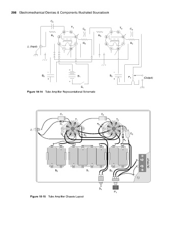
                   Figure 18-14 Tube Amplifier Representational Schematic


                                        C 1                        C 2
                                                  T 1                        T 2
                                        R 1                     R 3
                                               4  5                       4  5
                                              3   6                      3   6
                     J 1                      2   7                      2   7
                                               1  8                       1  8
                                                                                      C
                                                        R 2                            3
                                                                                 R 4


                                         +             +           +             +

                                                                                                  OUTPUT
                                   +             +           +             +

                                     B 2                 B 1            B 3


                                                                  S 1
                                                                           P 1
                     Figure 18-15 Tube Amplifier Chassis Layout
   331   332   333   334   335   336   337   338   339   340   341