
Page 335 - Electromechanical Devices and Components Illustrated Sourcebook
P. 335
Chapter 18 Electrical Schematics 297
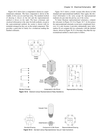
Figure 18-12 shows how a component is drawn in a repre- Figure 18-13 shows a triode vacuum tube drawn in both
sentational schematic. The basic component is shown in the standard and representational methods. Once again, the elec-
middle, in this case an octal base relay. The standard method trical information is the same except the representational
of drawing is shown on the left and the representational methods also provides the pin lay out of the socket.
method is shown on the right. The basic schematic and To better illustrate representational schematics, compare
electrical information is the same for both methods, except in the schematic in Figure 18-14 to Figure 18-7. At first glance
the representational method, the socket is shown with its the representational schematic seems more complicated; how-
terminals arranged as they are on the actual component. This ever, it is only because it provides substantially more infor-
provides a great deal of clarity for a technician reading the mation. If you compare the two schematics with the finished
finished schematic. chassis, shown in Figure 18-15, it becomes clear that the rep-
resentational method is much easier to follow.
4 5
3 6
2 7
1 8
Printed
Image
DPDT
Relay 6 5 4 3
Octal
Socket
7 8 1 2
Standard Drawing Components to Be Shown Representational Drawing
Figure 18-12 Standard versus Representational Relay Illustrations
Vacuum Tube
4 5
3 6
2 7
Octal Socket
1 8
Standard Drawing Components to Be Shown Representational Drawing
Figure 18-13 Standard versus Representational Vacuum Tube Illustrations