
Page 334 - Electromechanical Devices and Components Illustrated Sourcebook
P. 334
296 Electromechanical Devices & Components Illustrated Sourcebook
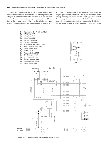
Figure 18-11 shows how the circuit is drawn using a rep- wire colors and gauges are clearly labeled. Components that
resentational schematic. Notice that all of the components are require greater detail, such as R and R are detailed in a sec-
1
2
arranged in principally the same locations as in the finished ondary drawing, as shown in the upper right hand corner.
chassis. The wires are routed using the same paths and loca- Even though there are a number of deviations from standard
tions as the finished chassis. Also note that all of the compo- symbols and methods, a technician presented with this infor-
nents are clearly labeled and a component list is present. The mation would have no difficulty deciphering the actual circuit.
C 1 Motor starter, 30 HP, 120 VAC Coil
F 1 2 Amp Type FNW
F 2 2 Amp Type FNW
3 Amp Type MDL
F 3
L 1 120 Volt Incandescent
L 2 120 Volt Incandescent 6 5 4 3
30 HP Motor, 480 VAC, 3 Phase
M 1
Delay On Relay, SPST, NO
R 1
R 2 Control Relay, DPDT
S 1 Switch, DPDT
Pressure Switch, SPST
S 2
S 3 Over Pressure Switch
S 4 Low Pressure Switch
S 5 Over temperature Switch 7 8 1 2
S 6 Emergency Stop Switch
R & R
T 1 Control Transformer 1 2
BLU 16 AWG
BRN 16 AWG BRN 16 AWG
R R
1 2
S
1
ORG 16 AWG
1 1
YEL 16 AWG
WHT ORG 16 AWG
WHT WHT 16 AWG
ORG VOL 16 AWG
YEL 16 AWG
L L
1
BRN 16 AWG
VOL 16 AWG
YEL 16 AWG
BRN 16 AWG
BLK 16 AWG
L L
BLK 16 AWG 2
RED 16 AWG
BLK 16 AWG
BLK 16 AWG BLU 16 AWG S 6
BLU 16 AWG
ORG 16 AWG
T RED 16 AWG S 2
1
BLK 16 AWG
F
3 BLU 16 AWG
ORG 16 AWG
F F S
1 2 3
S
BRN 16 AWG 4
BLK 16 AWG
S
5
BLK 16 AWG BLK 16 AWG C
BLK 16 AWG
GRN 12 AWG GRN 12 AWG
480 VAC BLK 10 AWG BLK 10 AWG
BLK 10 AWG BLK 10 AWG M 1
3 Phase BLK 10 AWG BLK 10 AWG
C
1
Figure 18-11 Air Compressor Representational Schematic