
Page 185 - Embedded Microprocessor Systems Real World Design
P. 185
counter is at OlFF and the interrupt occurs between the two instructions that reset
the bytes of the count. The high byte gets reset to 00 by the non-ISR code and then
the interrupt occurs. The low byte is incremented from FF to 00, causing the high
byte to be incremented to 01. The resulting count is 100 instead of 200 or 0000,
and the position count is completely off.
You can solve this problem by protecting the two resets with interrupt
disable/enable pairs. However, I worked on a system once where this solution intro-
duced an unacceptable delay in interrupt servicing. The fix in that case was to reset
the low byte first. Then, if the interrupt occurred between the resets, the low byte
would increment from 00 to 01, not affecting the high byte when the non-ISR code
resumed execution. This same principle applies any time you have two values that
are dependent on each other. Note that some compilers can produce this scenario
when working with values that are wider than the word width of the machine. You
can sometimes run into this problem with hardware that is wider than your word
width, such as a 16-bit timer connected to an &bit processor.
Another way to fix this specific problem is to have the interrupt code perform
both the reset and the increment. When the counter is to be reset, the non-ISR
code sets a flag. When the ISR is executed, it checks the flag. If the flag is not set,
it increments the count. If the flag is set, the ISR code zeros the count and clears
the flag. Note that this fix doesn’t work in some situations in which the two values
are in hardware registers.
Minimizing Lo w-Priority Interrupt Service Time
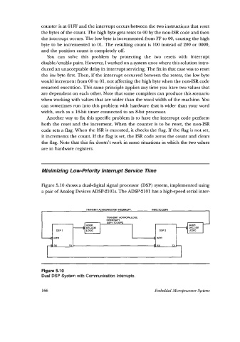
Figure 5.10 shows a dualdigital signal processor (DSP) system, implemented using
a pair of Analog Devices ADSP-2101s. The ADSP-2101 has a high-speed serial inter-
DSP 1 DSP 2
INTR D IMR
RX Tx RX Tx
Figure 5.10
Dual DSP System with Communication Interrupts.
166 Embedded Micropfocessm Systems