
Page 182 - Embedded Microprocessor Systems Real World Design
P. 182
Cumulative lime Errors
Imagine a system in which a timer generates an interrupt. Inside the ISR, the soft-
ware reloads the timer for the next interrupt. This might be done because the timer,
for whatever reason, is incapable of generating a regular output or because the time
between interrupts needs to vary with external events. Look at the following ISR
code description:
ISR entry.
Save registers on stack.
Calculate new timer value.
Store value to timer.
When the timer interrupt occurs, a varying amount of time will pass before the
ISR actually is executed, depending on what the CPU is doing. If a higher-priority
ISR is executing or if interrupts are not nested, then the variation in this delay can
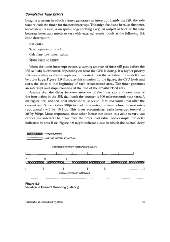
be quite large. Figure 5.9 illustrates this situation. In the figure, the CPU loads and
starts the timer at the beginning of each crosshatched area. The timer generates
an interrupt and stops counting at the end of the crosshatched area.
Assume that the delay between assertion of the interrupt and execution of
the instruction in the ISR that loads the counter is 300 microseconds (ps) (area A
on Figure 5.9) and the next interrupt must occur 10 milliseconds (ms) after the
current one. Since it takes 300ps to load the counter, the time before the next inter-
rupt actually will be 10.3ms. This error accumulates; each interrupt interval is
off by 300ps. More important, since other factors can cause this value to vary, you
cannot just subtract the error from the timer load value. For example, the delay
indicated by area B on Figure 5.9 might indicate a case in which the normal delay
=TIMER RUNNING
-1 =VARYING INTERRUPT LATENCY
INTENDED INTERRUPT IMERVALS (REGULAR)
A B C
I I I I I I I
ACTUAL INTERRUPT INTERVALS
Figure 5.9
Variation in Interrupt Servicing (Latency).
Interrupts in Embedded Systems 163