
Page 178 - Embedded Microprocessor Systems Real World Design
P. 178
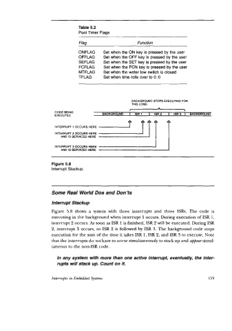
Table 5.2
                                    Pool Timer Flags

                                    Flag                      Function

                                    ONFLAG    Set when the ON key is pressed by the user
                                    OFFLAG     Set when the OFF key is pressed by the user
                                    SEFLAG     Set when the SET key is pressed by the user
                                    FCFLAG     Set when the FCN key is pressed by the user
                                    MTFLAG     Set when the water low switch is closed
                                    TFLAG      Set when time rolls over to 0 : 0


                                                           BACKGROUND STOPS EXECUTING FOR
                                                           THIS LONG
                                                          c
                         CODE BEING
                         EXECUTED             BACKGROUND   I   ISR1   I   ISR2   I  ISR3  I   BACKGROUND

                         INTERRUPT 1 OCCURS HERE
                         INTERRUPT  2 OCCURS HERE
                            AND IS SERVICED HERE

                         INTERRUPT  3 OCCURS HERE
                            AND IS SERWCED HERE

                        Figure 5.8
                        Interrupt Stackup.


                        Some Real World Dos and Don’ts

                        Interrupt Stackup
                        Figure  5.8  shows a  system with  three  interrupts  and  three  ISRs.  The  code  is
                        executing in the background when interrupt 1 occurs. During execution of ISR 1,
                        interrupt 2 occurs. As soon as ISR 1 is finished, ISR 2 will be executed. During ISR
                        2, interrupt 3 occurs, so ISR 2 is followed by  ISR 3. The background code stops
                        execution for the sum of the time it takes ISR 1, ISR 2, and ISR 3 to execute. Note
                        that the interrupts do not have to occur simultaneously to stack up and appear simul-
                        taneous to the non-ISR code.

                          In any system with more than one active interrupt, eventually, the inter-
                          rupts will stack up. Count on it.


                        Interrupts in Embedded Systems                                       159