
Page 285 - Embedded Microprocessor Systems Real World Design
P. 285
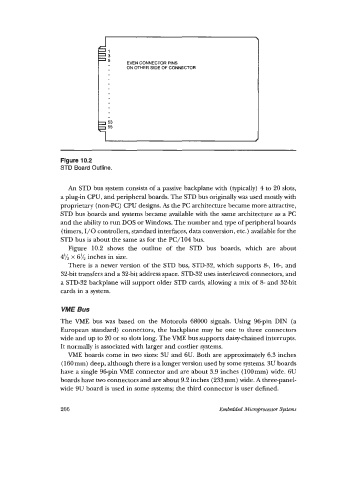
Figure 10.2
                   STD Board Outline.


                      An  STD bus system consists of a passive backplane with  (typically) 4 to 20 slots,
                   a plug-in CPU, and peripheral boards. The STD bus originally was used mostly with
                   proprietary (non-PC) CPU designs.  As the PC architecture became more attractive,
                   STD bus boards and systems became available with the same architecture as a PC
                   and the ability to run DOS or Windows. The number and type of peripheral boards
                    (timers, 1/0 controllers, standard interfaces, data conversion, etc.) available for the
                   STD bus is about the same as for the PC/104  bus.
                      Figure  10.2  shows  the  outline  of  the  STD  bus  boards,  which  are  about
                   4% x 6% inches in size.
                      There is a newer version of the STD bus, STD-32, which supports 8-, 16, and
                    32-bit transfers and a 32-bit address space. STD-32 uses interleaved connectors, and
                   a STD-32 backplane will support older STD cards, allowing a mix of 8- and 32-bit
                   cards in a system.


                    VME Bus
                   The VME  bus was  based  on  the  Motorola  68000  signals. Using  96-pin  DIN  (a
                   European standard)  connectors,  the backplane may  be one to  three  connectors
                   wide and up to 20 or so slots long. The VME bus supports daisy-chained interrupts.
                   It normally is associated with larger and costlier systems.
                      VME  boards come in two  sizes: 3U and 6U. Both are approximately 6.3 inches
                    (160 mm) deep, although there is a longer version used by some systems. 3U boards
                   have a single 96-pin VME connector and are about 3.9 inches (100mm) wide. 6U
                   boards have two connectors and are about 9.2 inches (233 mm) wide. A three-panel-
                   wide 9U board is used in some systems; the third connector is user defined.


                   266                                             Embedded Microprocessor Systems